
Fan

A fan and fan frame technology, applied in the field of fans with ribs, can solve the problems of inconvenience, difficulty in winding and fixing power supply wiring, high assembly, etc., and achieve the goals of reducing the axial height, improving the convenience of assembly, and reducing the axial height Effect

Active Publication Date: 2010-12-01
SUNONWEALTH ELECTRIC MACHINE IND
View PDF0 Cites 6 Cited by
  • Summary
  • Abstract
  • Description
  • Claims
  • Application Information

AI Technical Summary

Problems solved by technology

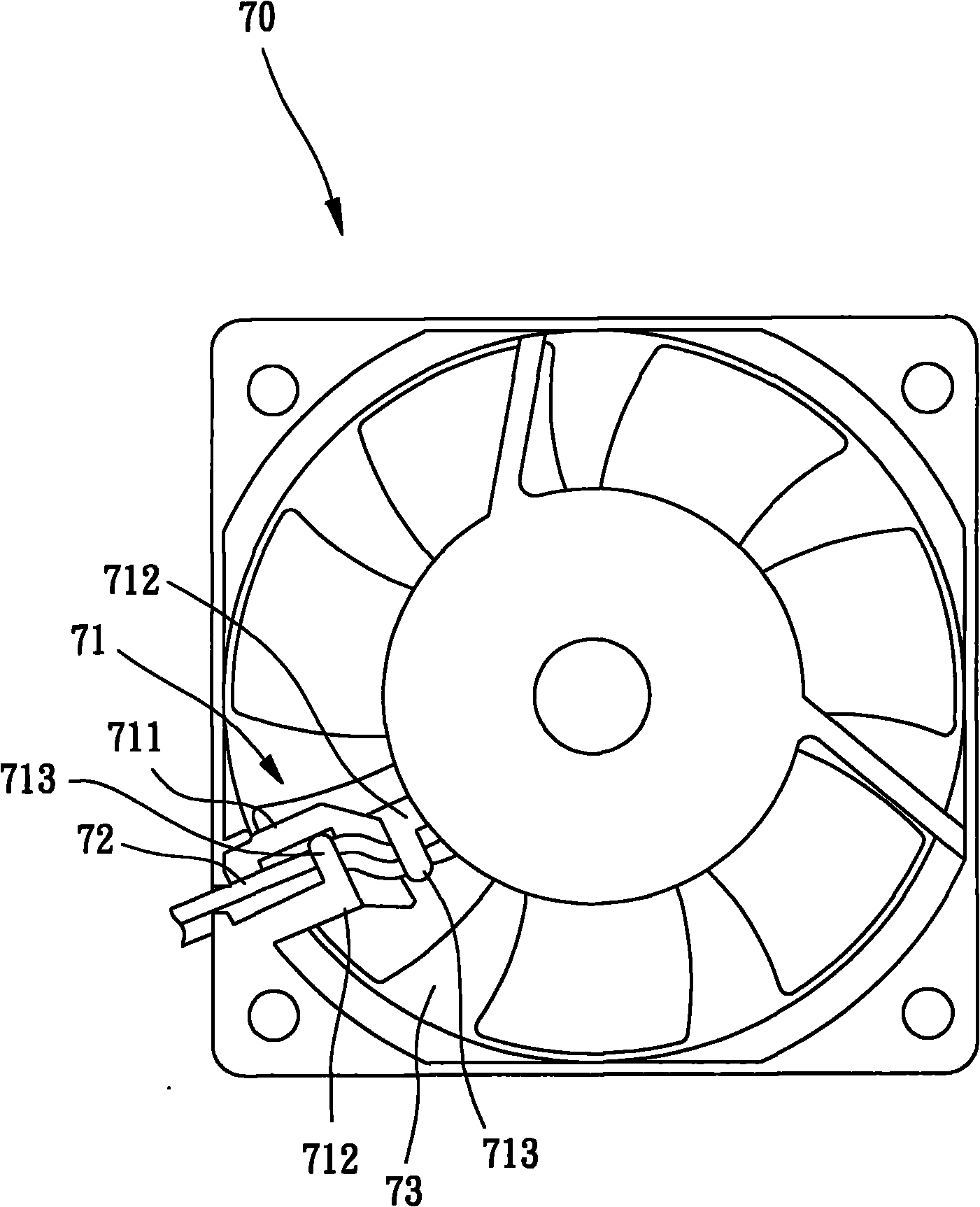
[0005] The invention provides a fan, which is used to solve the problems of high difficulty in winding and fixing the power wiring of the existing fan with ribs and inconvenient assembly, which is the main purpose of the invention

Method used


Image

  • Fan
  • Fan
  • Fan

Examples


Embodiment Construction

[0036] In order to make the above-mentioned and other objects, features and advantages of the present invention more comprehensible, the preferred embodiments of the present invention are specifically cited below, together with the accompanying drawings, and are described in detail as follows:

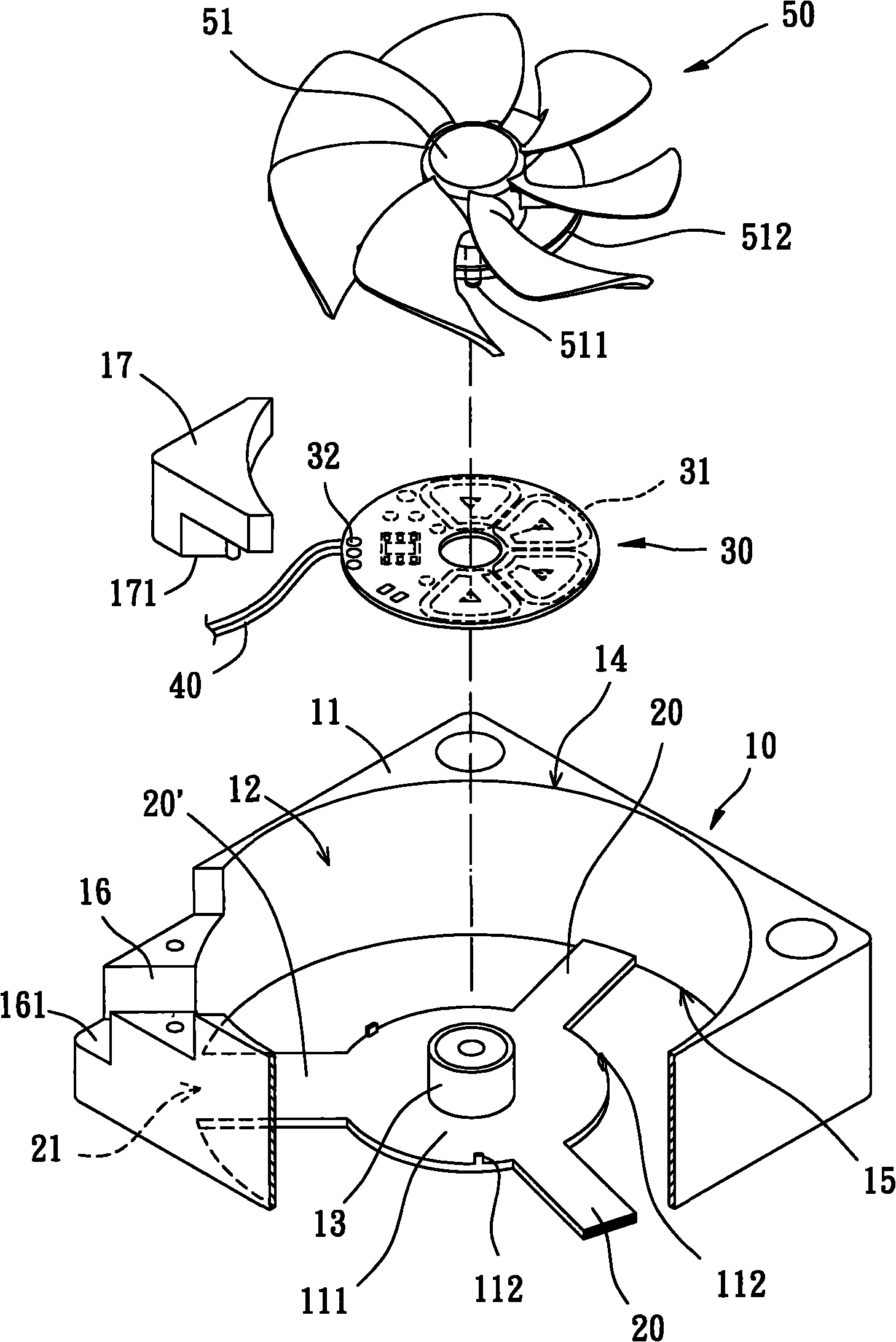
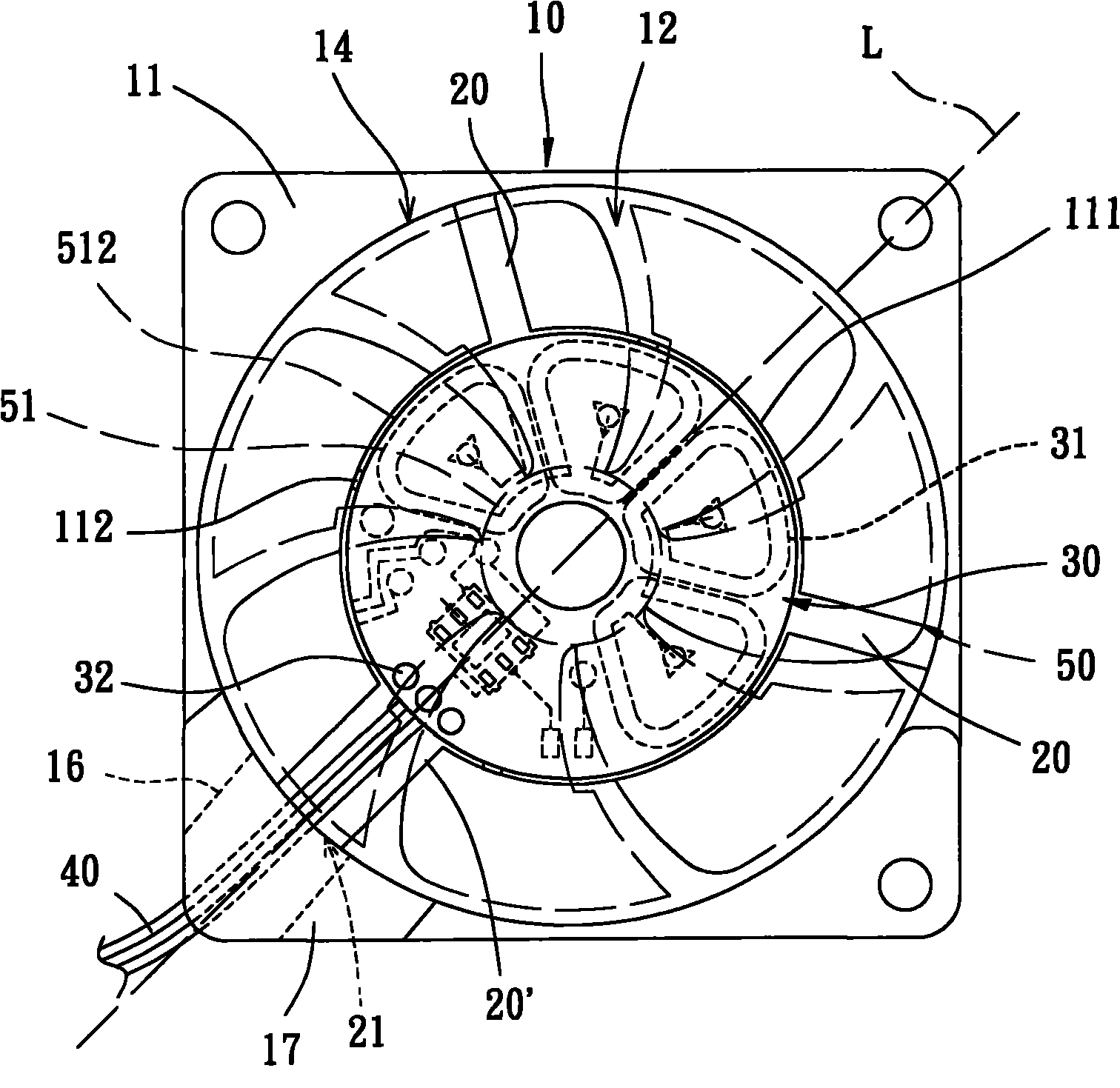
[0037] Please refer to figure 2 and image 3 As shown, the fan of the present invention at least includes a fan frame 10 , several connectors 20 , a base plate 30 , a power connection 40 and a fan wheel 50 . The fan frame 10 is a fan frame structure with ribs (or stationary vanes); the several connectors 20 (ie, ribs or stationary vanes) are located inside the fan frame 10; the base plate 30 is combined with the inside of the fan frame 10 for use To drive the fan wheel 50 to rotate; the power connection 40 is electrically connected to the base plate 30, and combined with one of the connectors 20 for external power supply; the fan wheel 50 is rotatably combined with the inside of the ...


PUM


Abstract

The invention relates to a fan comprising a fan frame, a plurality of connecting pieces, a substrate, a power-supply wiring and a fan wheel, wherein the fan frame is provided with a lead port; one of the connecting pieces is a wiring fixing part; the wiring fixing part is provided with a combining end facing the lead port; the combining end and the lead port are oppositely connected; the substrate is combined with the fan frame; the substrate is provided with an electric connection port; one end of the power-supply wiring is connected with the electric connection port, and the other end stretches through the lead port; and the fan wheel is rotatably combined at the inner side of the fan frame, thereby the wiring fixing part can be adjacent to the lead port to ensure that the power-supply wiring directly stretches through the lead port by the wiring fixing part so as to promote the assembling convenience of the power-supply wiring.

Description

technical field [0001] The invention relates to a fan, especially a fan with ribs (or stator blades) which is easy to install for power wiring. Background technique [0002] Existing fans usually have a power connection, and the location of the power connection must be properly arranged to ensure that the power connection can be effectively prevented from loosening or being involved in the fan during the actual operation of the fan, so that the fan can operate normally. Moreover, the common existing fans on the market can be roughly divided into two types, wherein the first type of existing fans does not have ribs (or stator blades) design, while the second type of existing fans has ribs (or Static blade) design, the power wiring of the two existing fans is handled differently. [0003] For example, such as China Taiwan Announcement No. 449682 "Ultra-Thin Cooling Fan Structure" invention patent and China Taiwan Announcement No. 443435 "Blower Fan Wire Buckle Structure Impro...

Claims


Application Information

Patent Timeline
Patent Type & Authority Applications(China)
IPC IPC(8): F04D25/08
Inventor 洪银树
Owner SUNONWEALTH ELECTRIC MACHINE IND
Learn More