Optical device module, optical transmitter and receiver, and optical receptacle

a technology of optical devices and optical receivers, applied in the direction of optical elements, semiconductor lasers, instruments, etc., can solve the problems of increasing the loss of optical connection, affecting the performance of optical connections, so as to increase the resistance to external electrical noise, reduce the proportion of metal components, and increase the insulating property

Active Publication Date: 2008-01-29
LUMENTUM JAPAN INC
View PDF6 Cites 23 Cited by
  • Summary
  • Abstract
  • Description
  • Claims
  • Application Information

AI Technical Summary

Benefits of technology

[0017]The present invention has as its object to provide an optical receptacle structure excellent in the EMI and EMS characteristics and superior in the optical connection characteristics under a transversal tensile stress to the optical fiber when connecting the optical connector, and higher in economic advantages and improved in ease of assembly.
[0019]By using a ceramic material for the leading end portion where the connector of the optical receptacle is connected, a high level of insulating property can be maintained, making it possible to increase the resistance to external electrical noise, such as electrostatic discharge. Because the proportion of metal component parts is reduced, it is possible to minimize the radiation of noise generated in the light-emitting device module or light-receiving device module. Because a ceramic material has high hardness and good machinability with high accuracy, it is possible to minimize deterioration in the optical connection characteristics under a transversal tensile stress to the optical fiber when connecting the optical connector.

Problems solved by technology

In the structure of a light-emitting device module or light-receiving device module for a conventional optical receptacle, in an optical transceiver which adopts this kind of module, problems described below are likely to occur.
As a result, EMI and EMS characteristics deteriorate.
However, because the resin material is inferior in hardness than a metal material, when a stress, which corresponds to a transversal tensile force to the optical fiber, is applied to the optical connector under the condition that the optical connector is connected to an optical receptacle type optical transceiver, that resin portion itself is deformed by the stress, thus increasing the optical connection loss.
In recent years, besides maintenance personnel skilled in this special field, an increasing number of general users handle optical fibers, and there has been higher demand for optical connection characteristics and resistance characteristics in handling optical fibers, which is undesirable.
In the case where the sleeve or the sleeve holder is made of a resin, when the optical connector is disconnected or connected, it sometimes occurs that the optical-connector ferrule, which is generally made of a hard substance, at the end of the optical connector contacts the resin sleeve or sleeve holder and scrapes the surface, with the result that scraping chips of the resin material are produced.
The scraping chips enter between the contact surfaces of the optical-connector ferrule and the stub ferrule of the light-emitting device module or light-receiving device module, involved in coupling of light, giving rise to an increase in optical connection loss at the contact surfaces and deteriorations in optical connection characteristics, such as an increase in reflected light.
In the above-mentioned structure, however, problems will arise as follows: (1) Because a large proportion of the structure is accounted for by metal parts, the optical transmitter or receiver tends to work as a radiation transmission antenna or a reception antenna and, as a result, the EMC characteristics deteriorate, and (2) Because a metal and a ceramic are used at the leading end portion of the receptacle where the connector is connected, on account of electrical noise entering from the connector side, the characteristics of the other component parts deteriorate.

Method used


Image

  • Optical device module, optical transmitter and receiver, and optical receptacle
  • Optical device module, optical transmitter and receiver, and optical receptacle
  • Optical device module, optical transmitter and receiver, and optical receptacle

Examples


embodiment 1

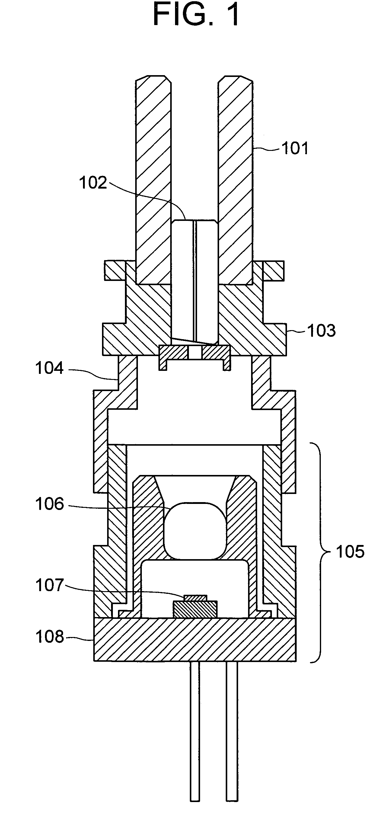
[0027]FIG. 1 is a diagram showing a first embodiment of the present invention. Incidentally, the basic function of each portion is the same as the corresponding portion in the related art shown in FIG. 4 unless otherwise described. The nonmetallic sleeve 101 holds the optical-connector ferrule and the stub ferrule 102 to be connected, and is in a unified structure of the sleeve cover 401 and the sleeve 402 in FIG. 4 described above. The sleeve 101 connects two cores about 10 μm in diameter, which serve as waveguides located along the central axes of the optical-connector ferrule and the stub ferrule 102, with accuracy of the external dimensions of the two ferrules. On the other hand, with regard to the accuracy of the internal diameter of the ferrules, machining work with μm-level accuracy is required. The stub ferrule 102 and the holder 103 are press-fit and fixed in such a way as to obtain stable positional accuracy.

[0028]The nonmetallic sleeve 101 is fixed to the holder 103 with ...

embodiment 2

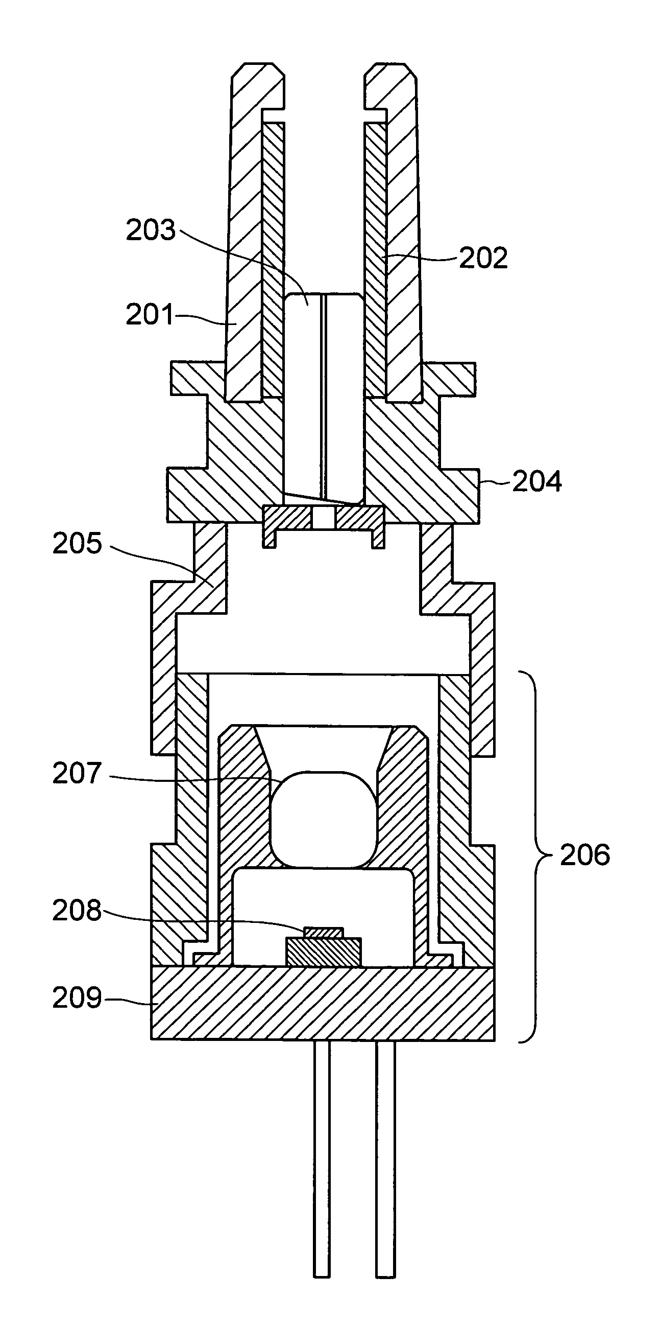
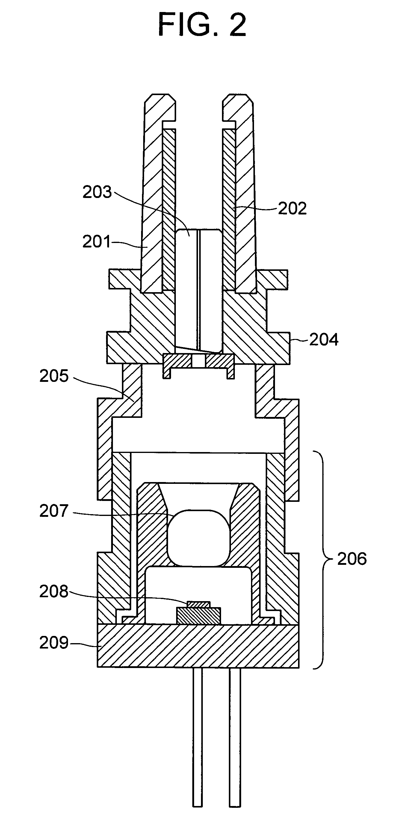
[0031]FIG. 2 is a diagram showing a second embodiment of the present invention. As shown in FIG. 2, a stub ferrule 203 is press-fit and fixed to the holder 204 to realize stable positional accuracy. Note that in this embodiment, the sleeve 202 may be a slot sleeve or a precision sleeve without an ordinary slot structure.

[0032]In this embodiment, a sleeve cover 201 is press-fit and fixed to the holder to protect the sleeve 202. The holder 204 is joined to the adapter 205 by YAG welding, and the adapter 205 is further joined to further joined to the light-emitting device or light-receiving device 206 by YAG welding.

[0033]Incidentally, the sleeve 202, the sleeve cover 201, and the stub ferrule 203 are made of a ceramic, and the holder 204 and the adapter 205 are made of a metal. In other words, the structure in FIG. 2 is similar to the structure shown in FIG. 4, except that a ceramic sleeve cover 201 is used in place of the metal sleeve cover 401. In addition, a reference numeral 207 d...

embodiment 3

[0038]FIGS. 3A and 3B are diagrams showing a third embodiment of the present invention. FIG. 3A shows an optical transceiver including a light-emitting device module or a light-receiving device module for an optical receptacle, which has been described in the above-described embodiment. FIG. 3B shows the structure of the optical receptacle block when the optical-fiber-side optical connector is connected to the optical transceiver in FIG. 3A. The light-emitting device module or the light-receiving device module 303 with a ceramic sleeve 301 having the features of the sleeve shown in the first embodiment is fixed to the optical transceiver 304 by using an insulation retaining material 305. Numeral 302 denotes a light-emitting device or a light-receiving device, and 306 denotes a stub ferrule.

[0039]As shown in FIG. 3B, when connecting an optical connector, the optical-fiber-side optical connector 307 is inserted into the optical receptacle portion of the optical transceiver, and the op...


PUM


Abstract

An optical device module includes a stub ferrule for guiding a laser light to an optical fiber to be connected, a sleeve for holding an optical-connector ferrule of the optical fiber to be connected and the stub ferrule, a holder for fixing the stub ferrule and the sleeve, and an adapter for connecting the holder and an optical module, in which the sleeve is formed by a nonmetallic material, reducing the structure of metal portion and restraining the antenna effect when electromagnetic noise enters.

Description

INCORPORATION BY REFERENCE[0001]The present application claims priorities from Japanese applications JP 2005-184250 filed on Jun. 24, 2005, JP 2004-263189 filed on Sep. 10, 2004, the contents of which are hereby incorporated by reference into this application.BACKGROUND OF THE INVENTION[0002]The present invention relates to an optical device module used in an optical receptacle type optical transceiver, such as a light-emitting device module or a light-receiving device module, and also to an optical transceiver of light receptacle structure in which the above-mentioned optical device module is mounted.[0003]With the increase in the amount of transmission in recent years due to the diffusion of the Internet, for example, optical transceivers have come to be used as articles of everyday use. As for the mode of using optical transceivers in this case, it is most effective to use optical receptacle type optical transceivers, which can be directly detached and connected to the panel of a...

Claims


Application Information

Patent Timeline
Patent Type & Authority Patents(United States)
IPC IPC(8): G02B6/36G02B6/42H01L31/0232H01S5/022
CPCG02B6/4206G02B6/421G02B6/4292
Inventor ENDOU, FUTOSHIMOROHASHI, NAOFUMIMIURA, ATSUSHI
Owner LUMENTUM JAPAN INC
Why Eureka
Try Eureka