Composite fan and frame thereof

a technology of composite fans and fan frames, which is applied in the direction of machines/engines, stators, liquid fuel engines, etc., can solve the problems of increasing production costs, heat tends to reduce the stability and efficiency of electronic products, and the electronic products generate heat as they operate, so as to improve the structure intensity and enhance the convenience of assembly

Active Publication Date: 2007-01-04
DELTA ELECTRONICS INC
View PDF7 Cites 23 Cited by
  • Summary
  • Abstract
  • Description
  • Claims
  • Application Information

AI Technical Summary

Benefits of technology

[0010] In view of the foregoing, the invention is to provide a composite fan and a fan frame thereof capable of enhancing the assembling convenience and obtaining the better structure intensity without using extra screws.
[0013] As mentioned hereinabove, the composite fan and the frame thereof according to the invention have the first protrusion portion and the first recess portion such that the first frame and the second frame may be easily assembled. Compared to the prior art, the fan and the frame thereof according to the invention have the advantages of being assembled easily without using screws and of having the better structure intensity.

Problems solved by technology

However, the electronic product generates heat as it operates.
The heat tends to reduce the stability and the efficiency of the electronic product if the heat is not properly dissipated, or may even bum out the electronic product.
As the results, it increases the production cost.
Furthermore, the screw 13 is usually thin and small and tends to be lost so that a tool has to be used during the processes of assembling of the fans.
Thus, the fans cannot be easily assembled.
As the results, the assembling processes are complicated and inconvenient.
Therefore, using multiple long screws can not be performed in the conventional composite fan 1.

Method used


Image

  • Composite fan and frame thereof
  • Composite fan and frame thereof
  • Composite fan and frame thereof

Examples


first embodiment

[0026]FIG. 3 is a schematic view showing a composite fan frame 2 according to a first embodiment of the invention. Referring to FIG. 3, the composite fan frame 2 includes a first frame 21 and a second frame 22.

[0027] The first frame 21 has preferably four lateral sides and a first surface 211, which is a bottom surface of the first frame 21. The first surface 211 has a first protrusion portion 212 and a second protrusion portion 213 which are disposed oppositely. Herein, the first surface 211 has a substantially tetragonal shape. The first protrusion portion 212 and the second protrusion portion 213 are respectively disposed at two opposite comers of the first surface 211. In this embodiment, the cross-section of each of the first protrusion portion 212 and the second protrusion portion 213 is a substantially inverse trapezoid. The first protrusion portion 212 and the second protrusion portion 213 respectively have first inclined surfaces 2121 and 2131.

[0028] The second frame 22 h...

second embodiment

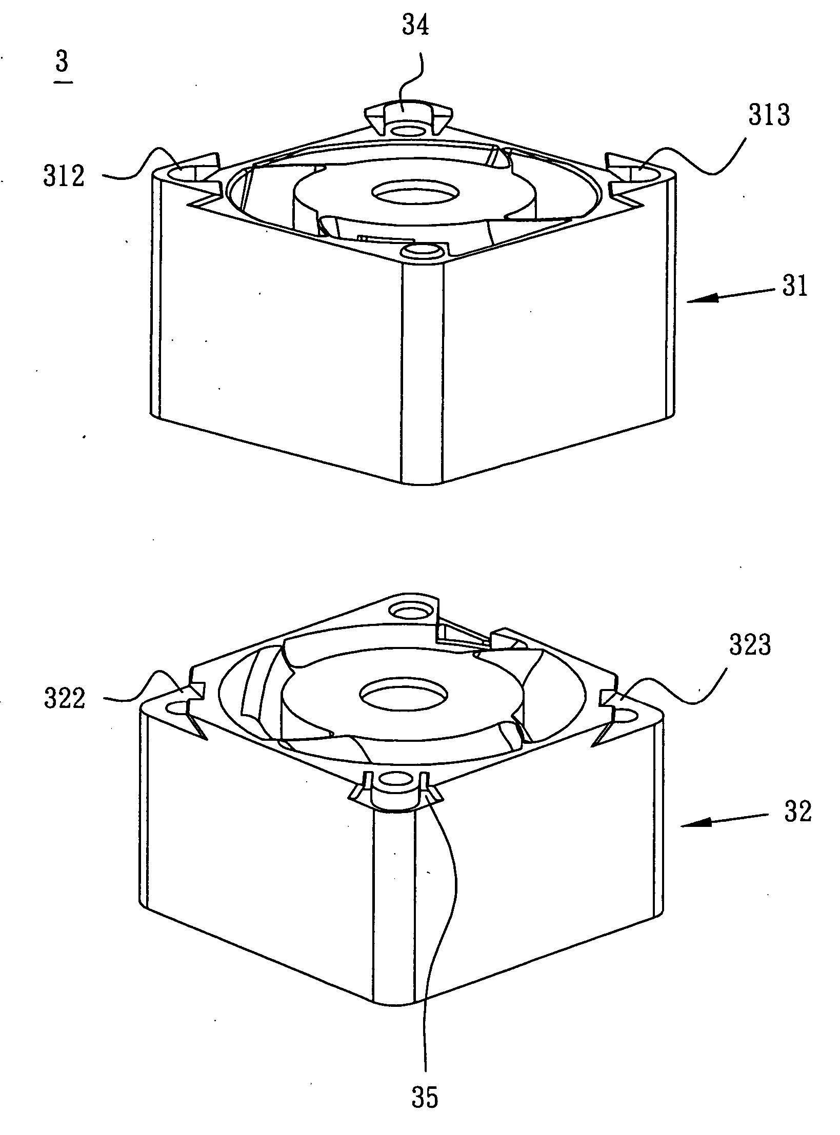
[0035]FIGS. 7 and 8 are schematic views showing a composite fan frame 3 before and after being assembled according to a second embodiment of the invention. The composite fan frame 3 includes a first frame 31 and a second frame 32.

[0036] It is noted that the composite fan frame 3 of this embodiment is different from the composite fan frame 2 of the first embodiment (FIG. 3) because a first protrusion portion 312 and a second protrusion portion 313 of the first frame 31 have substantially triangular shapes, and are respectively disposed at two opposite comers of a surface of the first frame 31. The second frame 32 is formed with a first recess portion 322 and a second recess portion 323, which are disposed oppositely and with respect to the first protrusion portion 312 and the second protrusion portion 313 of the first frame 31. The first recess portion 322 and the second recess portion 323 are respectively disposed at two opposite comers of a surface of the second frame 32.

[0037] S...


PUM


Abstract

A composite fan frame includes a first frame and a second frame. The first frame has a first surface formed with at least one first protrusion portion. The second frame has a second surface formed with at least one first recess portion. When the first surface touches the second surface, the first protrusion portion is inserted into the first recess portion along a predetermined sliding direction such that the first frame and the second frame are combined. Also, a composite fan having the composite fan frame is disclosed.

Description

[0001] This Non-provisional application claims priority under U.S.C.§ 119(a) on Patent Application No(s). 094122140, filed in Taiwan, Republic of China on Jun. 30, 2005, the entire contents of which are hereby incorporated by reference. BACKGROUND OF THE INVENTION [0002] 1. Field of Invention [0003] The invention relates to a fan and a fan frame thereof, and in particular to a composite fan and a fan frame thereof. [0004] 2. Related Art [0005] With the progress of the technology, the efficiency of the electronic product is gradually enhanced. However, the electronic product generates heat as it operates. The heat tends to reduce the stability and the efficiency of the electronic product if the heat is not properly dissipated, or may even bum out the electronic product. Thus, most electronic products use fans to make the electronic products operate within a predetermined operating temperature range. However, a single fan sometimes cannot provide sufficient airflow. So, two or more th...

Claims


Application Information

Patent Timeline
Patent Type & Authority Applications(United States)
IPC IPC(8): F01D1/02
CPCH05K7/20172F04D29/646F04D19/007
Inventor HSU, SHUO-SHIUCHANG, SHUN-CHENHUANG, WEN-SHILIN, LI-CHEN
Owner DELTA ELECTRONICS INC
Why Eureka
Try Eureka