Clamp apparatus

a technology of clamping apparatus and clamping chamber, which is applied in the direction of soldering apparatus, manufacturing tools,auxillary welding devices, etc., can solve the problems of increasing the number of parts needed to construct the clamping apparatus, reducing the ease of assembly of the clamping apparatus when the clamping apparatus is manufactured, etc., to achieve the effect of improving the ease of assembly facilitating and smoothly carrying out the clamping operation, and simplifying the structure of the clamping apparatus

Inactive Publication Date: 2009-04-30
SMC CORP
View PDF14 Cites 26 Cited by
  • Summary
  • Abstract
  • Description
  • Claims
  • Application Information

AI Technical Summary

Benefits of technology

[0007]A general object of the present invention is to provide a clamp apparatus, which is capable of reliably and smoothly carrying out a clamping operation on a workpiece, in which the structure of the clamp apparatus is simplified, and ease of assembly of the clamp apparatus is improved.

Problems solved by technology

As a result, the number of parts needed to construct the clamp apparatus increases, and the structure thereof is complex, which decreases the ease of assembly thereof when the clamp apparatus is manufactured.

Method used


Image

  • Clamp apparatus
  • Clamp apparatus
  • Clamp apparatus

Examples


Embodiment Construction

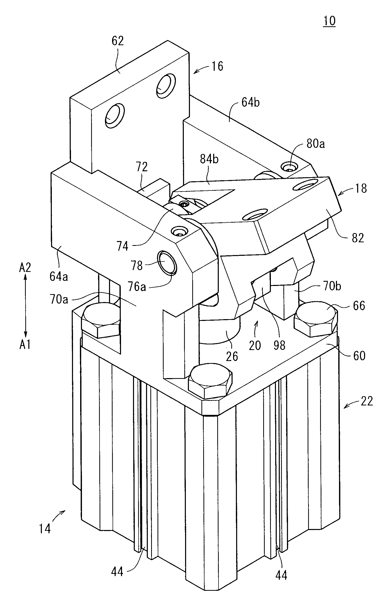
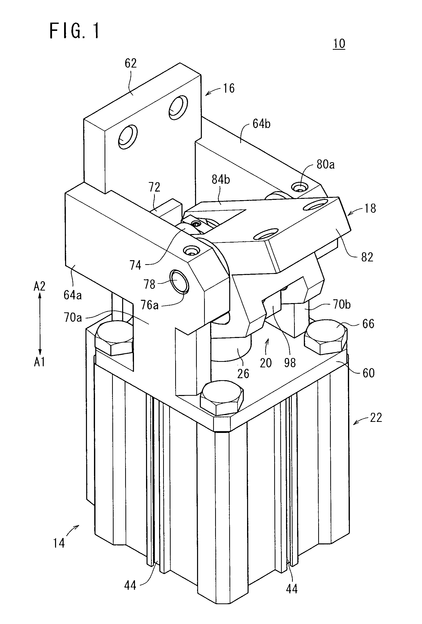
[0023]In FIG. 1, reference numeral 10 indicates a clamp apparatus according to an embodiment of the present invention.

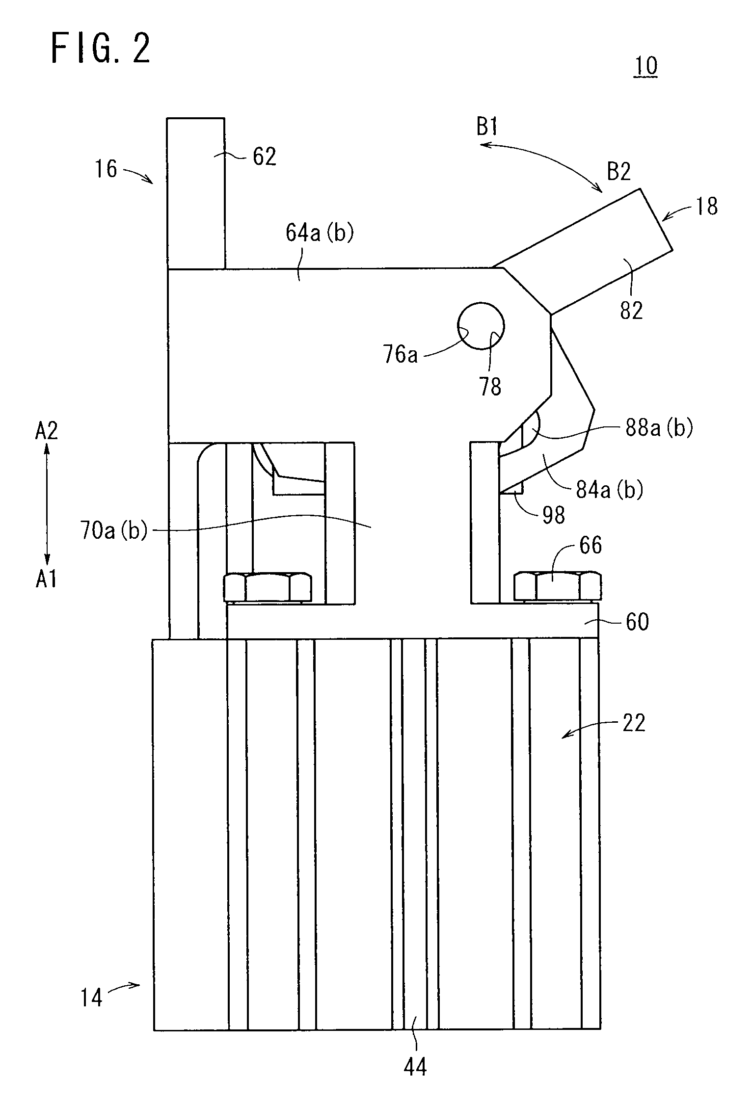
[0024]As shown in FIGS. 1 through 5, the clamp apparatus 10 includes a cylinder mechanism (cylinder) 14 with a piston 12 installed therein, a housing (main body) 16 connected to the cylinder mechanism 14, a clamp arm 18 that is retained rotatably with respect to the housing 16, and a driving force transmitting mechanism 20 that rotates the clamp arm 18 under a driving action of the cylinder mechanism 14.

[0025]The cylinder mechanism 14 comprises a cylinder tube 22 formed in a hollowed shape, the piston 12, which is disposed displaceably inside the cylinder tube 22, a head cover 24 that closes one end of the cylinder tube 22, and a rod cover 28 disposed at the other end side of the cylinder tube 22, which supports a piston rod 26 connected to the piston 12.

[0026]The cylinder tube 22 is formed with a rectangular shape in cross section and a cylinder hole 30 penetrates t...


PUM


Abstract

The present invention relates to a clamp apparatus equipped with a cylinder mechanism having a piston. A driving force of the cylinder mechanism is transmitted to a clamp arm, which is retained on a housing through a block body and a link pin that make up a driving force transmitting mechanism, the clamp arm being rotated through a predetermined angle. The block body includes a rotatably supported roller. The block body is guided along an axial direction by displacement of the roller, while the roller is rotated along a guide member of the housing.

Description

BACKGROUND OF THE INVENTION[0001]1. Field of the Invention[0002]The present invention relates to a clamp apparatus, which is capable of clamping a workpiece via a rotatable clamp arm that is rotated through a predetermined angle under a displacement operation of a piston.[0003]2. Description of the Related Art[0004]Heretofore, for example, when constituent parts of an automobile or the like are welded, a clamp apparatus has been used for clamping the parts.[0005]The clamp apparatus, for example as disclosed in U.S. Pat. No. 5,503,378, comprises a main body equipped with a piston that is displaced under the supply of a pressure fluid, a pair of clamp arms which are retained rotatably with respect to the main body, and a toggle link mechanism through which a driving force from the main body is transmitted to the clamp arm. In addition, rotating rollers that make up part of the toggle mechanism are inserted into guide grooves formed respectively on both side surfaces of the main body. ...

Claims


Application Information

Patent Timeline
Patent Type & Authority Applications(United States)
IPC IPC(8): B25B5/04
CPCB25B5/087B23K37/00B23K37/04
Inventor HARA, KOJIKANDA, KOUICHIROU
Owner SMC CORP
Why Eureka
Try Eureka