Brake master cylinder

a brake master and cylinder technology, applied in the field of hydraulic braking devices, can solve the problems of increasing the difficulty of assembling the brake pad may be worn away, and the brake pad is thinned, so as to improve the reliability of the brake master cylinder, improve the sealing effect of hydraulic oil, and improve the assembly convenience

Active Publication Date: 2012-06-21
HENG KUO
View PDF7 Cites 24 Cited by
  • Summary
  • Abstract
  • Description
  • Claims
  • Application Information

AI Technical Summary

Benefits of technology

[0035]By comparing with the conventional brake master cylinder, the brake master cylinder of the invention does not only have beauty, but also improves the assembly convenience and increases the sealing effect for hydraulic oil under the condition of whether there is the function of automatically filling hydraulic oil, thereby greatly improving the reliability of the brake master cylinder.

Problems solved by technology

Moreover, after performing braking motion for several times, the brake pad may be worn away (the brake pad is thinned).
Consequently, it does not only influence the beauty of the brake master cylinder, but also increases the difficulty of assembling the brake master cylinder.
Moreover, the sealing effect of hydraulic oil is relatively not good enough.

Method used


Image

  • Brake master cylinder
  • Brake master cylinder
  • Brake master cylinder

Examples


first embodiment

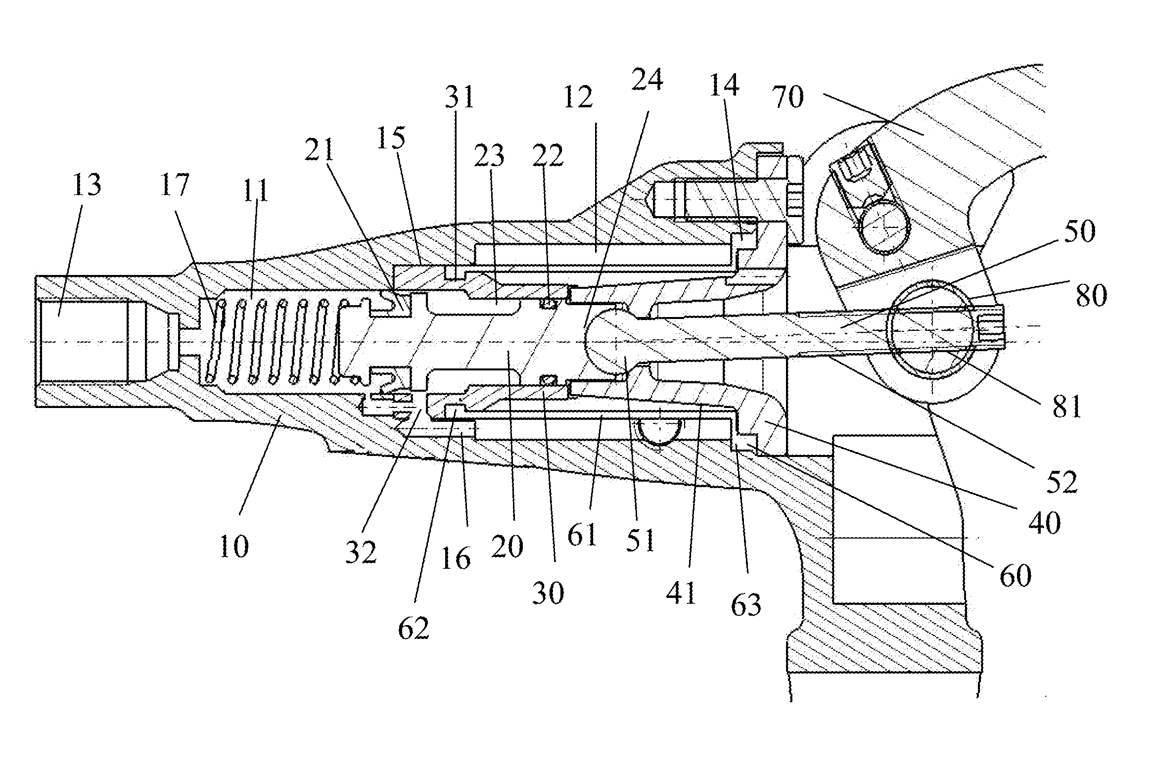
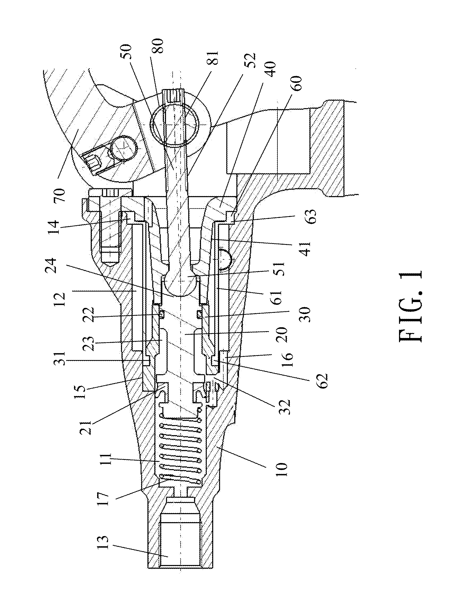
[0040]With reference to FIG. 1 for a cross-sectional drawing of an axial structure of a brake master cylinder in accordance with the invention is depicted. The brake master cylinder of the invention is to integrally dispose a main oil cylinder 11 and an oil storing space 12 at a handlebar base 10 for installing a brake handlebar 70. The oil storing space 12 is disposed to an axial position of the main oil cylinder 11 of the handlebar base 10. One end of the handlebar base 10 is provided with an oil outlet 13, which relatively corresponds to the main oil cylinder 11, connected to a hydraulic pipe (not shown in the figure). One end of the handlebar base 10 is provided with an installation hole 14 corresponding to the oil storing space 12. In addition, a piston capable of being driven by the brake handlebar 70 is disposed in the main oil cylinder 11.

[0041]A sleeve 30 engaged with the main oil cylinder 11 is disposed in the oil storing space 12 of the handlebar base 10. One end of the p...

second embodiment

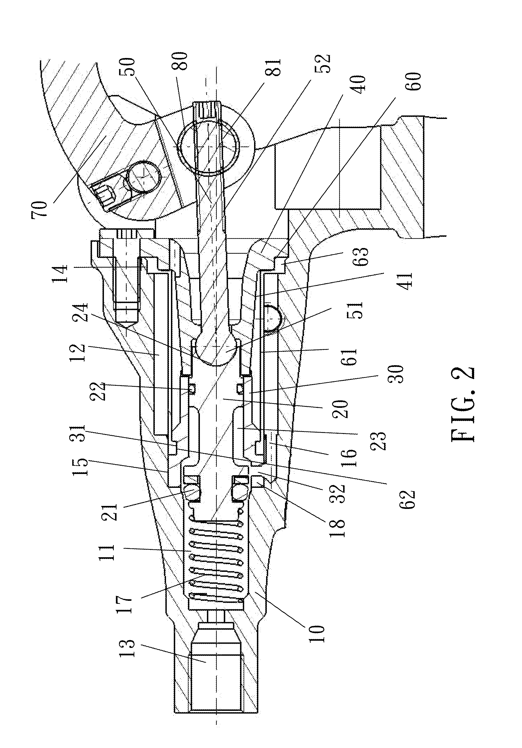
[0054]Moreover, with reference to FIG. 2 for a cross-sectional drawing of a structure in accordance with the invention, the first rubber ring 21 can also be a circular rubber ring. The handlebar base 10 further has an oil-return section 18, in which an inner diameter is relatively larger than an external diameter of the first rubber ring 21, formed at a position of relatively disposing the first oil-return hole 16 of the main oil cylinder 11 to relatively speed up the first rubber ring 21 passing through the first oil-return hole 16, thereby increasing the braking sensitivity.

[0055]Under the structural forms of two different embodiments shown in FIG. 1 and FIG. 2, the second rubber ring 22 can be a circular rubber ring that is mainly utilized to prevent hydraulic oil from being leaked through the passing place between the piston 20 and the sleeve and to steady the motion of the piston 20.

[0056]The piston 20 is provided with a necking section 23 between the first rubber ring 21 and t...


PUM


Abstract

A brake master cylinder of the invention is to dispose a main oil cylinder and an oil storing space on a handlebar base. In addition, a sleeve engaged with the main oil cylinder is disposed in the oil storing space. The one end of the oil storing space has a fastening seat passed by a draw bar linked to the brake handlebar, and a positioning sheath of the fastening seat is utilized to engage with the sleeve. A leakage prevention component is disposed between the fastening seat and the handlebar base. A bushing integrally extended from the leakage prevention component is utilized to encapsulate the positioning sheath of the fastening seat and the sleeve. Accordingly, the brake master cylinder having convenient assembly and better sealing effect for hydraulic oil is obtained.

Description

BACKGROUND OF THE INVENTION[0001]1. Field of the Invention[0002]The present invention relates to a hydraulic braking device, and more particularly to a brake master cylinder that is conveniently assembled and having better sealing effect for hydraulic oil.[0003]2. Description of the Related Art[0004]A hydraulic brake apparatus utilized in a motorcycle or a bicycle can be taken as one of hydraulic equipment that is in widespread use. A brake master cylinder driven by a brake handlebar is disposed to a handgrip place of the hydraulic brake apparatus. In addition, a braking caliper is disposed to wheels through a hydraulic pipe. When a rider presses the brake handlebar, a piston relatively disposed in a main oil cylinder of the brake master cylinder is driven by the brake handlebar to go forward. Hydraulic oil within the main oil cylinder is pushed into a sub-oil cylinder of the braking caliper to allow a brake pad of the sub-oil cylinder to move toward the brake disc. The brake pad is...

Claims


Application Information

Patent Timeline
Patent Type & Authority Applications(United States)
IPC IPC(8): B62L3/02B60T11/10B60T7/08
CPCB60T7/102B60T11/232B60T11/18B60T11/165
Inventor WANG, CHUN-CHIN
Owner HENG KUO
Why Eureka
Try Eureka