Driving force transmission mechanism

Inactive Publication Date: 2011-03-31
KEIHIN CORP
View PDF17 Cites 23 Cited by
  • Summary
  • Abstract
  • Description
  • Claims
  • Application Information

AI Technical Summary

Benefits of technology

[0009]A general object of the present invention is to provide a driving force transmission mechanism, in which positioning of a drive gear and a driven gear can easily be carried out when the drive gear and the dr

Problems solved by technology

However, with the driving force transmission mechanism according to the prior art, in the case that a clearance is set such that an enmeshed state between the plurality of teeth provided on the small gear of the output gear, the tooth thickness of which is small, and the teeth provided on th

Method used


Image

  • Driving force transmission mechanism
  • Driving force transmission mechanism
  • Driving force transmission mechanism

Examples


Embodiment Construction

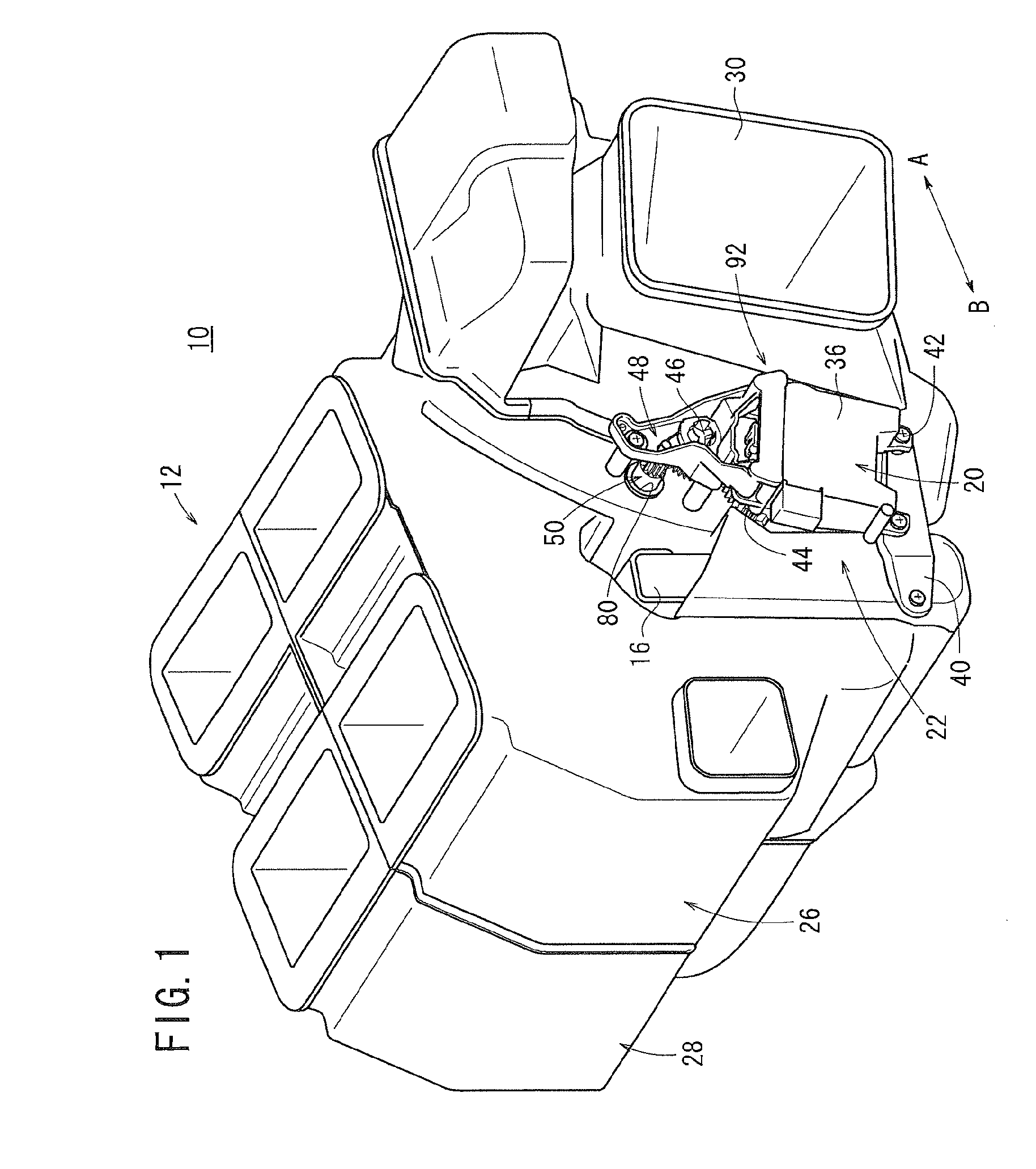
[0024]In FIG. 1, reference numeral 10 indicates a vehicular air conditioning apparatus to which a driving force transmission mechanism according to an embodiment of the present invention is applied.

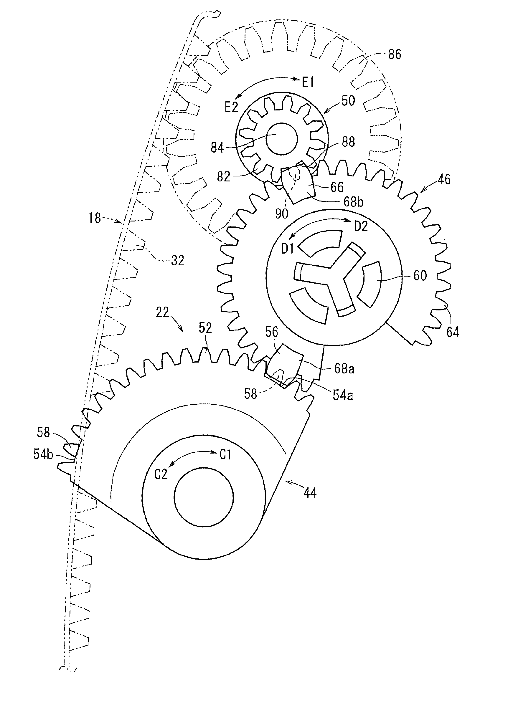
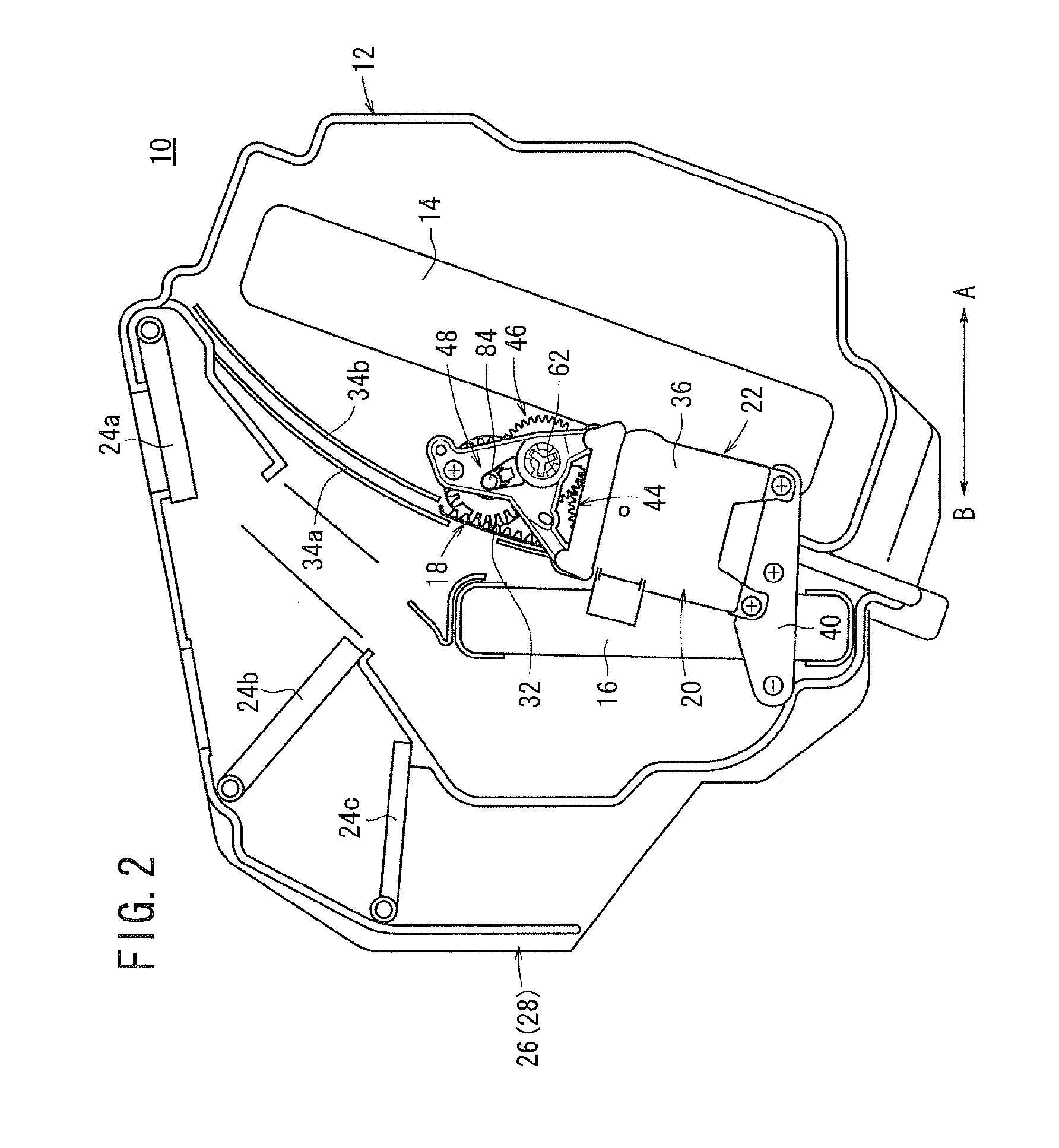
[0025]As shown in FIGS. 1 and 2, the vehicular air conditioning apparatus 10 includes a casing 12 constituted by a plurality of respective air passages therein, an evaporator 14 arranged in the interior of the casing 12 that cools the air, a heater core 16 for heating the air, an air mixing damper (switching damper) 18 that performs heat exchange by means of the evaporator 14 and the heater core 16 on air that is introduced to the interior of the casing 12, and which mixes at a predetermined mixing ratio cool air and warm air having been adjusted in temperature, thereby producing mixed air, and a driving force transmission mechanism 22 that transmits a driving force of a drive source (driving section) 20, which is disposed on a side surface of the casing 12, to the air mixing damper 18 fo...


PUM


Abstract

A driving force transmission mechanism is equipped with a first gear attached to a drive source, a second gear enmeshed with the first gear, and a damper shaft enmeshed mutually with the second gear and with a rack member of an air mixing damper. A first locator part formed on the second gear is inserted in a first locator groove in the first gear, while additionally, a second locator part is inserted with respect to a second locator groove in a damper gear. Further, a first narrow tooth formed on the first gear enmeshes with a meshing groove of the first locator part, whereas a second narrow tooth formed on the damper gear enmeshes with another meshing groove of the second locator part.

Description

CROSS-REFERENCE TO RELATED APPLICATION[0001]This application is based upon and claims the benefit of priority from Japanese Patent Application No. 2009-220733 filed on Sep. 25, 2009, of which the contents are incorporated herein by reference.BACKGROUND OF THE INVENTION[0002]1. Field of the Invention[0003]The present invention relates to a driving force transmission mechanism for transmitting and outputting an output force of a driving section via a drive gear and a driven gear.[0004]2. Description of the Related Art[0005]Heretofore, in a vehicular air conditioning apparatus, which is mounted in a passenger vehicle, cool air that is cooled by an evaporator serving as a cooling means and warm air that is heated by a heater core serving as a heating means are mixed together in a housing thereof by adjusting a degree of opening of an air mixing damper, and such mixed air is blown out selectively by opening and closing outlet doors, which are provided with respect to outlet ports dispose...

Claims


Application Information

Patent Timeline
IPC IPC(8): F16H55/02
CPCB60H1/00664F16H19/00Y10T74/19642F16H2057/0056F16H19/04F16H19/001F16H55/17
Inventor IKEDA, SHINTARO
Owner KEIHIN CORP
Why Eureka
Try Eureka