Optical device module, optical transmitter and receiver, and optical receptacle
- Summary
- Abstract
- Description
- Claims
- Application Information
AI Technical Summary
Benefits of technology
Problems solved by technology
Method used
Image
Examples
embodiment 1
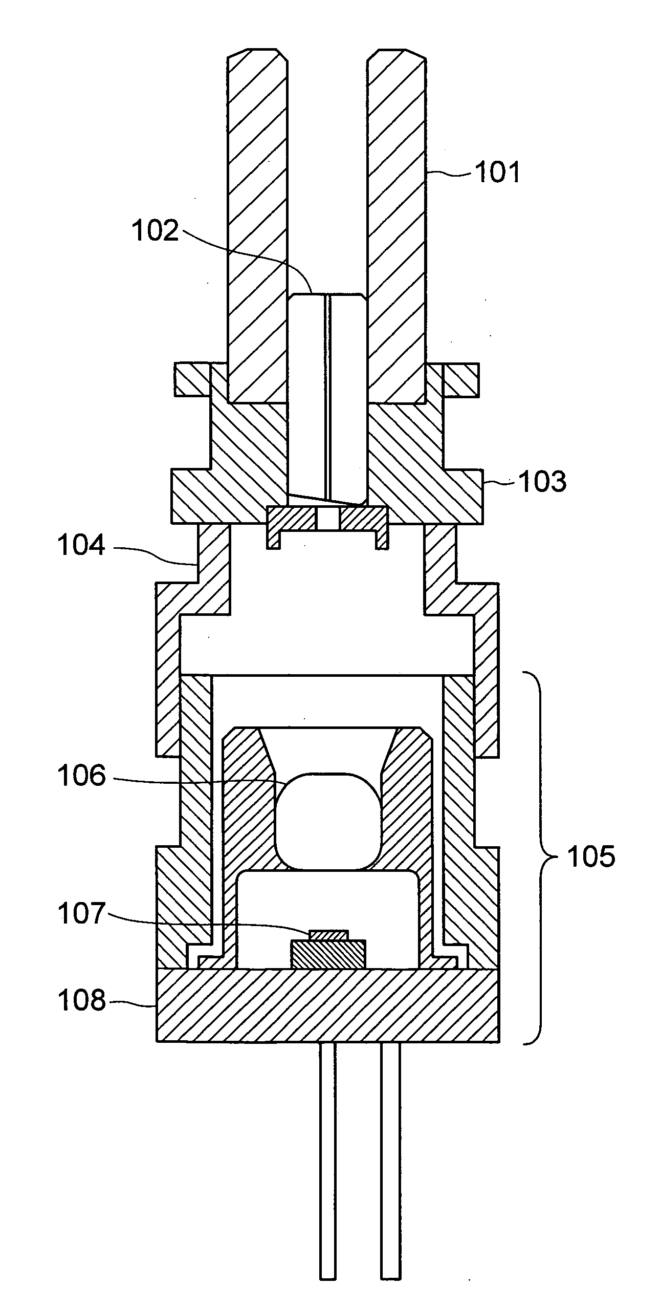
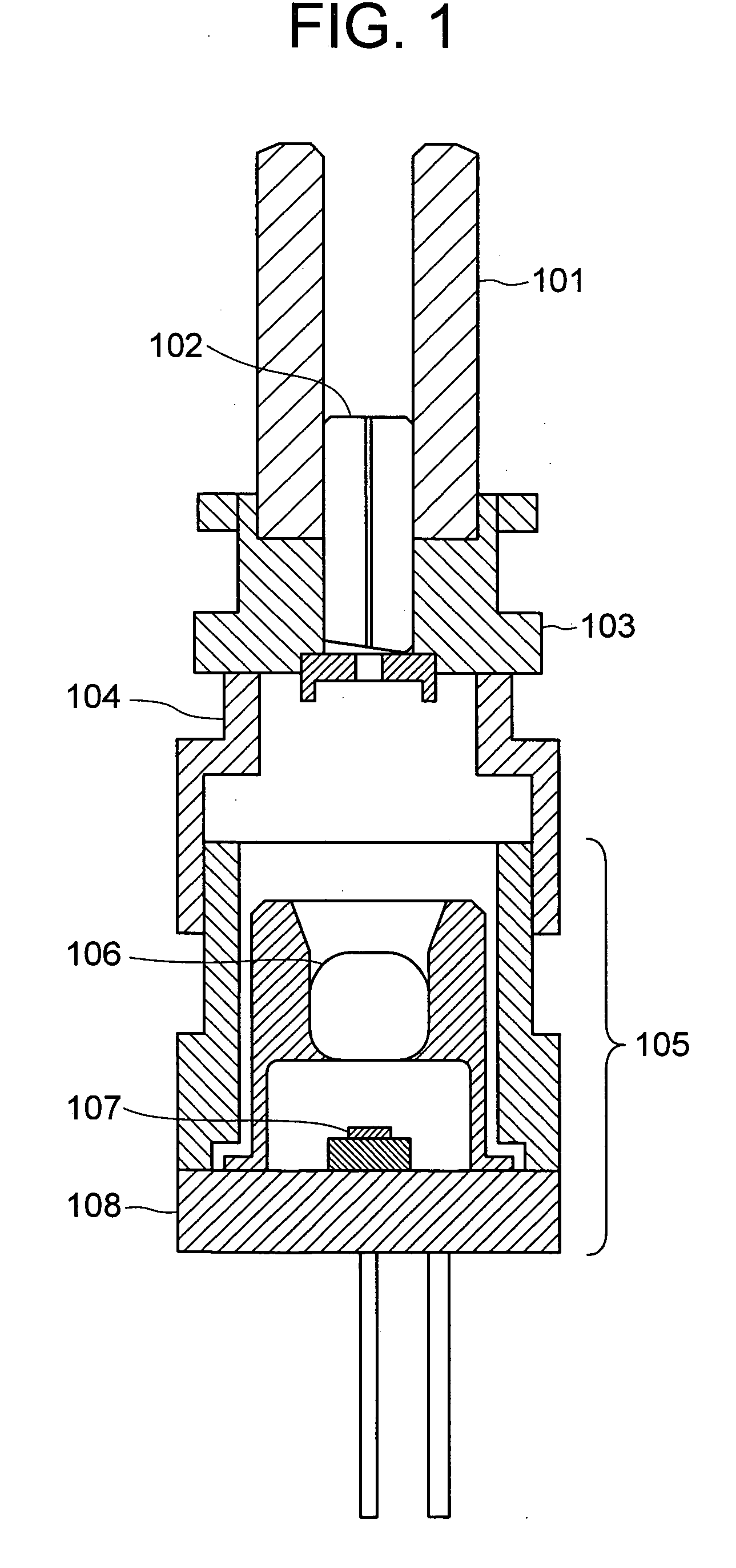
[0027]FIG. 1 is a diagram showing a first embodiment of the present invention. Incidentally, the basic function of each portion is the same as the corresponding portion in the related art shown in FIG. 4 unless otherwise described. The nonmetallic sleeve 101 holds the optical-connector ferrule and the stub ferrule 102 to be connected, and is in a unified structure of the sleeve cover 401 and the sleeve 402 in FIG. 4 described above. The sleeve 101 connects two cores about 10 μm in diameter, which serve as waveguides located along the central axes of the optical-connector ferrule and the stub ferrule 102, with accuracy of the external dimensions of the two ferrules. On the other hand, with regard to the accuracy of the internal diameter of the ferrules, machining work with μm-level accuracy is required. The stub ferrule 102 and the holder 103 are press-fit and fixed in such a way as to obtain stable positional accuracy.
[0028] The nonmetallic sleeve 101 is fixed to the holder 103 wit...
embodiment 2
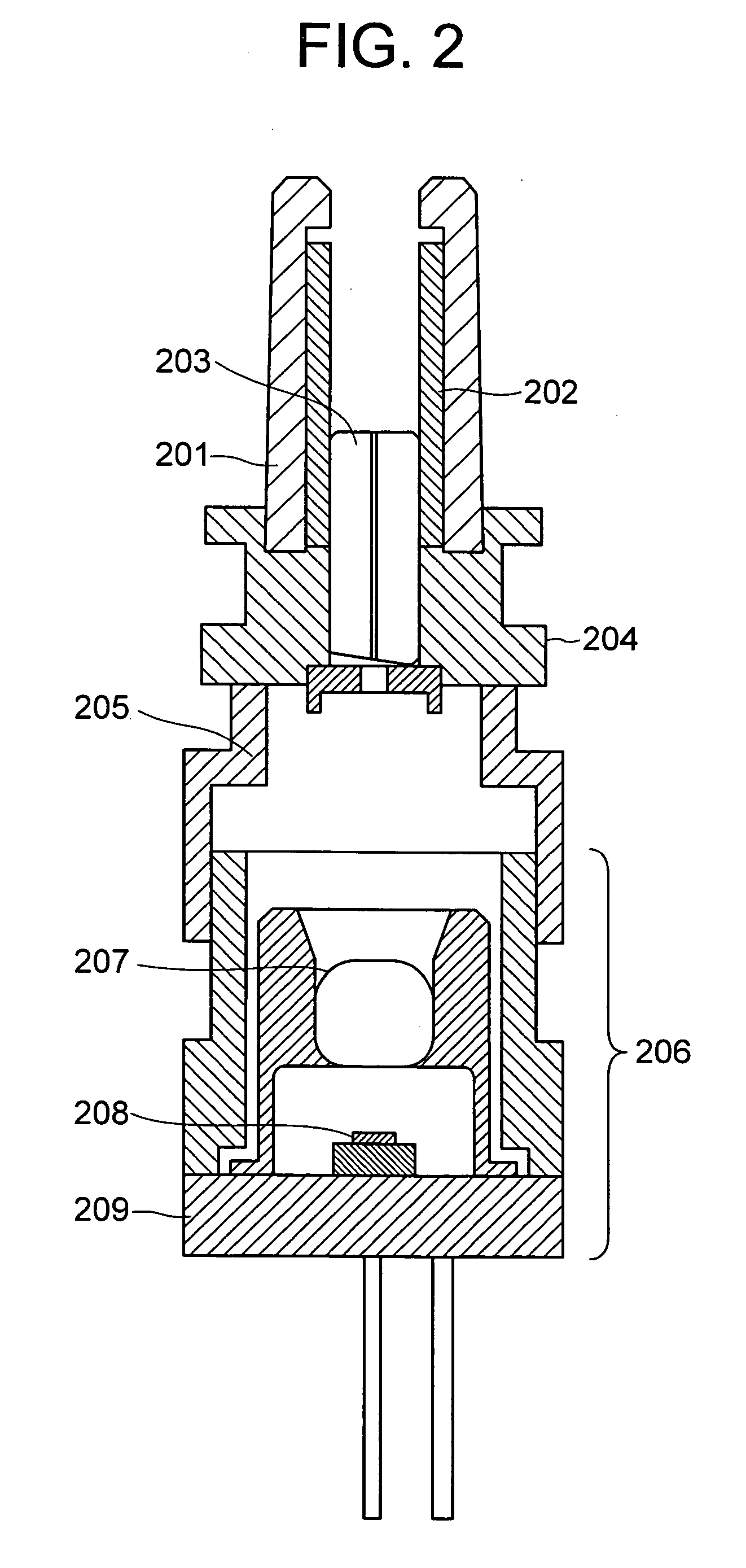
[0031]FIG. 2 is a diagram showing a second embodiment of the present invention. As shown in FIG. 2, a stub ferrule 203 is press-fit and fixed to the holder 204 to realize stable positional accuracy. Note that in this embodiment, the sleeve 202 may be a slot sleeve or a precision sleeve without an ordinary slot structure.
[0032] In this embodiment, a sleeve cover 201 is press-fit and fixed to the holder to protect the sleeve 202. The holder 204 is joined to the adapter 205 by YAG welding, and the adapter 205 is further joined to further joined to the light-emitting device or light-receiving device 206 by YAG welding.
[0033] Incidentally, the sleeve 202, the sleeve cover 201, and the stub ferrule 203 are made of a ceramic, and the holder 204 and the adapter 205 are made of a metal. In other words, the structure in FIG. 2 is similar to the structure shown in FIG. 4, except that a ceramic sleeve cover 201 is used in place of the metal sleeve cover 401.
[0034] In this embodiment, Zirconi...
embodiment 3
[0038]FIGS. 3A and 3B are diagrams showing a third embodiment of the present invention. FIG. 3 shows an optical transceiver including a light-emitting device module or a light-receiving device module for an optical receptacle, which has been described in the above-described embodiment. FIG. 3B shows the structure of the optical receptacle block when the optical-fiber-side optical connector is connected to the optical transceiver in FIG. 3A. The light-emitting device module or the light-receiving device module 303 with a ceramic sleeve 301 having the features of the sleeve shown in the first embodiment is fixed to the optical transceiver 304 by using an insulation retaining material 305. Numeral 302 denotes a light-emitting device or a light-receiving device.
[0039] As shown in FIG. 3B, when connecting an optical connector, the optical-fiber-side optical connector 307 is inserted into the optical receptacle portion of the optical transceiver, and the optical-connector ferrule 310 is ...
PUM
 Abstract
Description
Claims
Application Information
 - R&D
- Intellectual Property
- Life Sciences
- Materials
- Tech Scout
- Unparalleled Data Quality
- Higher Quality Content
- 60% Fewer Hallucinations
Browse by: Latest US Patents, China's latest patents, Technical Efficacy Thesaurus, Application Domain, Technology Topic, Popular Technical Reports.
© 2025 PatSnap. All rights reserved.Legal|Privacy policy|Modern Slavery Act Transparency Statement|Sitemap|About US| Contact US: help@patsnap.com


