Water heater with water leakage detecting function

A water heater and detector technology, applied to water heaters, by detecting the appearance of fluid at the leak point, the direction of the fluid heater, etc., it can solve the problems of the influence of the surrounding environment, the complex structure of the water heater, and the large space occupied, and achieve a small volume. , the structure is simple, the effect of reducing the impact

Inactive Publication Date: 2010-12-01
BSH ELECTRICAL APPLIANCES JIANGSU
2 Cites 12 Cited by

AI-Extracted Technical Summary

Problems solved by technology

However, the above-mentioned water leakage detection devices can only detect water leakage after a period of time when the inner tank leaks, and during thi...

Method used

Owing to having adopted audio frequency detector, in case liner leaks, just can detect corresponding audio frequency change in time, thereby take corresponding measure to reduce the influence that causes to surrounding environment because of wat...

Abstract

The invention discloses a water heater which comprises an internal bladder, a water inlet pipe, a water outlet pipe, a heat source and an audio detector, wherein the internal bladder is used for containing a certain amount of water which can be heated; the water inlet pipe and the water outlet pipe are communicated with the internal bladder for transferring water flowing into the internal bladder and water flowing out of the internal bladder; the heat source is used for heating water in the internal bladder; and the audio detector is used for detecting audio variation caused by water leakage of the internal bladder. Because the audio detector is adopted, once the internal bladder leaks water, the corresponding audio variation can be detected in time, so that corresponding measures are taken for reducing the influence of water leakage on the ambient environment.

Application Domain

Technology Topic

Image

  • Water heater with water leakage detecting function
  • Water heater with water leakage detecting function
  • Water heater with water leakage detecting function

Examples

  • Experimental program(1)

Example Embodiment

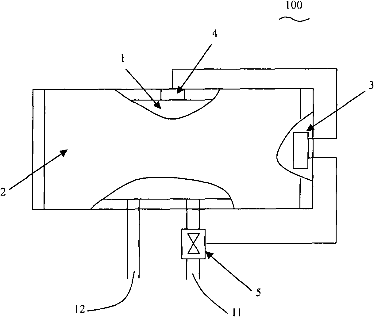
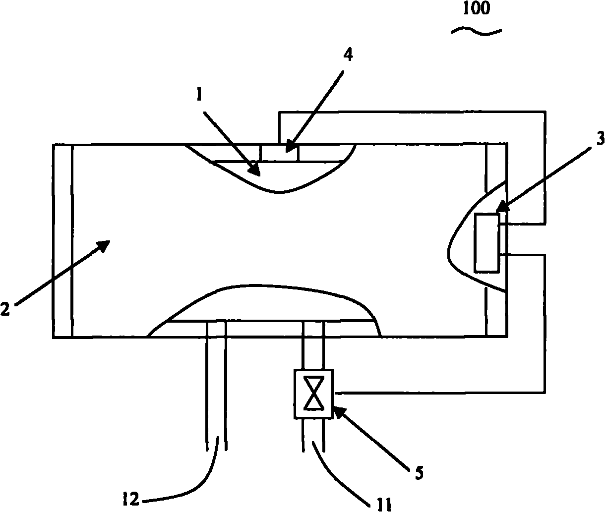
[0016] figure 1 A specific embodiment of the water heater of the present invention is shown. In this embodiment, the water heater 100 is a horizontal type, which includes an inner tank for storing heated water 1, an outer shell covering the inner tank 1, 2, formed between the inner tank 1 and the outer shell 2 filled with foam The insulation layer of the material (not labeled). The liner 1 is roughly cylindrical, and it is usually made of ferrous metal, such as steel, iron, and the like. The inner tank 1 includes a water inlet pipe 11 for introducing cold water into the inner tank and a water outlet pipe 12 for discharging heated water. The water heater 100 also includes a heat source 6 for heating cold water, which can take various forms. Taking an electric water heater as an example, a flange can be installed at one longitudinal end of the inner tank 1, an electric heating pipe is installed on the flange and extends into the water stored inside the inner tank, and the heating pipe may include a Impedance resistance wire, the positive and negative terminals of the resistance wire are arranged on the flange plate and connected with the AC power supply of 220V or 110V. Of course, for other forms of water heaters, such as gas-fired water heaters, the liquid in the inner tank can be heated through the combustion chamber provided outside the inner tank.
[0017] In this embodiment, an audio detector 4 is arranged on the outer wall of the inner tank 1, and it can also be arranged at any position between the inner tank 1 and the outer shell 2. The audio detector 4 includes a piezoelectric element 41 for emitting and receiving sound waves. It is well known to those skilled in the art that the piezoelectric unit is mainly composed of materials such as ceramics or crystal crystals, which deform after being stressed and generate a corresponding electric potential. A water shutoff device is provided on the water inlet pipe 11. In this embodiment, the water shutoff device is an electromagnetic valve (electromagnetic valve) 5. As is well known to those skilled in the art, a solenoid valve usually includes a valve body, a coil wound on the valve body, and a valve core that can move linearly within the valve body. A magnetic field is generated by applying current to a coil wound on the solenoid valve body, thereby driving the valve core to move linearly. In this embodiment, the movement direction of the valve core may be perpendicular to the water inlet pipe 11. The water heater 100 also includes a control system 3, which can be a circuit board integrated with a number of electronic control components, and the circuit board can be arranged on a flange.
[0018] With reference figure 2 As shown, the control system 3 is electrically connected to the audio detector 4 and the solenoid valve 5. In this embodiment, the control system 3 includes a controller 31 that controls the operation of the solenoid valve 5, a drive circuit 32 that drives the audio detector 4 to emit sound waves, and electronic components such as an amplifier 33 and a comparator 34. The controller 31 may be a microprocessor, and the microprocessor may include a central processing unit (Central Processing Unit, CPU), a read-only memory module (read-only memory, ROM), and a random access memory (RAM). , Timing module, A/D converter, and several input/output ports, etc. Of course, the controller 31 may also adopt other forms of integrated circuits, such as Application Specific Integrated Circuit (ASIC) or Field Programmable Gate Array (FPGA). When the audio detector 4 needs to be activated, the controller 31 outputs a control signal to the driving circuit 32 through the output port. The driving circuit 32 then outputs an alternating voltage signal to the audio sensor 4, and the piezoelectric unit 41 in the audio sensor 4 is correspondingly applied with alternating stress to vibrate, thereby outputting a sound wave of a specific frequency. The frequency of the sound wave is related to the applied voltage and is preset.
[0019] After the emitted sound wave hits the outer wall of the inner liner 1, it will bounce back and be received by the audio detector 4. The piezoelectric unit 41 is squeezed and deformed by the pressure of the sound wave to generate a corresponding voltage signal. The voltage signal is amplified by the amplifier 33 and compared with a preset threshold in the comparator 34. It is easy for those skilled in the art to understand that the threshold is used to characterize the limit value of the frequency of the reflected sound wave received by the piezoelectric unit when the tank leaks, and it has a certain functional relationship with the frequency of the sound wave emitted by the piezoelectric unit. The functional relationship is mainly summarized through experiments. When the outer surface of the inner tank is intact, the voltage signal representing the frequency of the reflected sound wave is lower than the preset threshold; but if there are holes on the outer surface of the inner tank 1, that is, when the inner tank is corroded and water leakage occurs, the reflected sound wave is The frequency has changed. At this time, the voltage signal representing the frequency of the reflected sound wave will be greater than or equal to the preset threshold. In this way, the comparator 34 will output a signal to the controller 31, such as a high level signal, the controller 31 Subsequently, a current is applied to the coil of the solenoid valve 5 to drive the valve core to move and block the flow of water in the water inlet pipe 11.
[0020] As a preferred embodiment, the controller 31 can also control the heat source 6. Taking an electric water heater as an example, the controller 31 is connected to a temperature sensor (not shown) for detecting the water temperature. When it is found that the water temperature has been heated to a preset temperature, the controller 31 cuts off the current supplied to the heating tube to stop heating. It should be noted that the above-mentioned embodiments are the preferred or preferred embodiments of the present invention. That is to say, the structure of the electric water heater of the present invention is not limited to the above-mentioned embodiments. Simple changes made to the above-mentioned embodiments are all included in the present invention. Within the protection scope of the claims. For example, in other embodiments, the piezoelectric unit may only be used as an element for emitting sound waves, and the audio detector further includes a condenser microphone to receive reflected sound waves and generate corresponding electrical signals.
[0021] Due to the use of audio detectors, once the inner tank leaks, the corresponding audio changes can be detected in time, so that corresponding measures can be taken to reduce the impact on the surrounding environment due to water leakage; in addition, compared to the existing technology The water collection basin and the audio detector have a simple structure and a small volume, which will not bring trouble to the design and manufacture of the water heater.

PUM

no PUM

Description & Claims & Application Information

We can also present the details of the Description, Claims and Application information to help users get a comprehensive understanding of the technical details of the patent, such as background art, summary of invention, brief description of drawings, description of embodiments, and other original content. On the other hand, users can also determine the specific scope of protection of the technology through the list of claims; as well as understand the changes in the life cycle of the technology with the presentation of the patent timeline. Login to view more.

Similar technology patents

Improved image segmentation training method based on full convolutional neural network

InactiveCN107862695AProminent lesionReduce the impactImage enhancementImage analysisSkin melanomaLesion segmentation
Owner:UNIV OF ELECTRONIC SCI & TECH OF CHINA

Combination of sulfonamide compound and tafluprost

InactiveUS20140018350A1Good effectReduce the impactBiocideOintment deliveryTherapy medicationBenzyl group
Owner:SANTEN PHARMA CO LTD +1

Classification and recommendation of technical efficacy words

  • Simple structure
  • Reduce the impact

Microlithographic projection exposure apparatus

InactiveUS20050068499A1Simple structureReliable and low-maintenance operationProjectorsPhotomechanical exposure apparatusCamera lensPhysics
Owner:CARL ZEISS SMT GMBH
Why Eureka
Try Eureka