Optical fiber grating measurement method for monitoring embankment section settlement

A technology of settlement monitoring and optical fiber grating, which is applied in the field of measurement of embankment section settlement, can solve the problem of low cost, achieve low cost, expand the application field, and improve the effect of measurement accuracy

Inactive Publication Date: 2010-12-01
NANJING HYDRAULIC RES INST
View PDF5 Cites 18 Cited by
  • Summary
  • Abstract
  • Description
  • Claims
  • Application Information

AI Technical Summary

Problems solved by technology

[0005] The technical problem to be solved by the present invention is to overcome the existing problems in the measurement of the settlement of the existing embankment section, and provide a method for measuring the settlement of the embankment section by using the current advanced distributed optical fiber sensing technology. A measuring device, a measuring method, and a measu

Method used


Image

  • Optical fiber grating measurement method for monitoring embankment section settlement
  • Optical fiber grating measurement method for monitoring embankment section settlement
  • Optical fiber grating measurement method for monitoring embankment section settlement

Examples


Embodiment 1

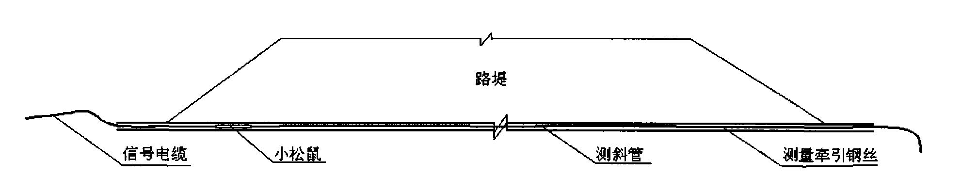
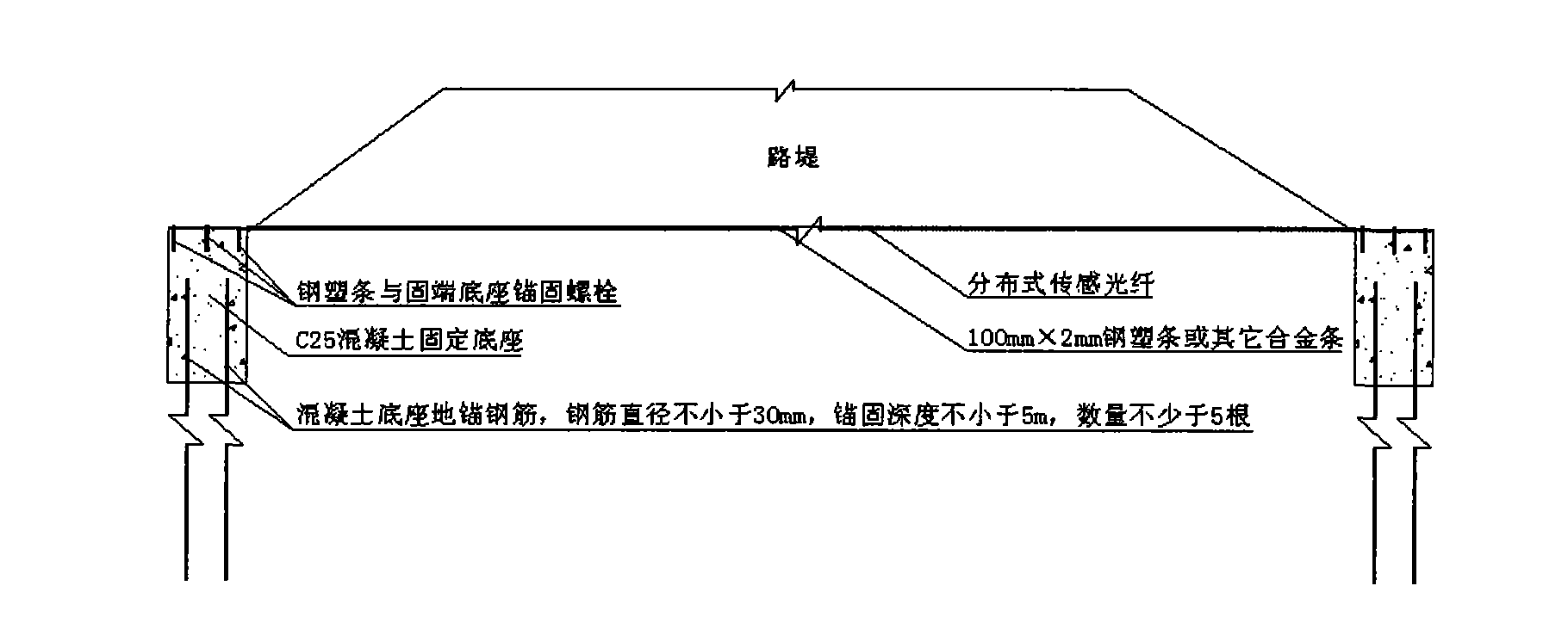
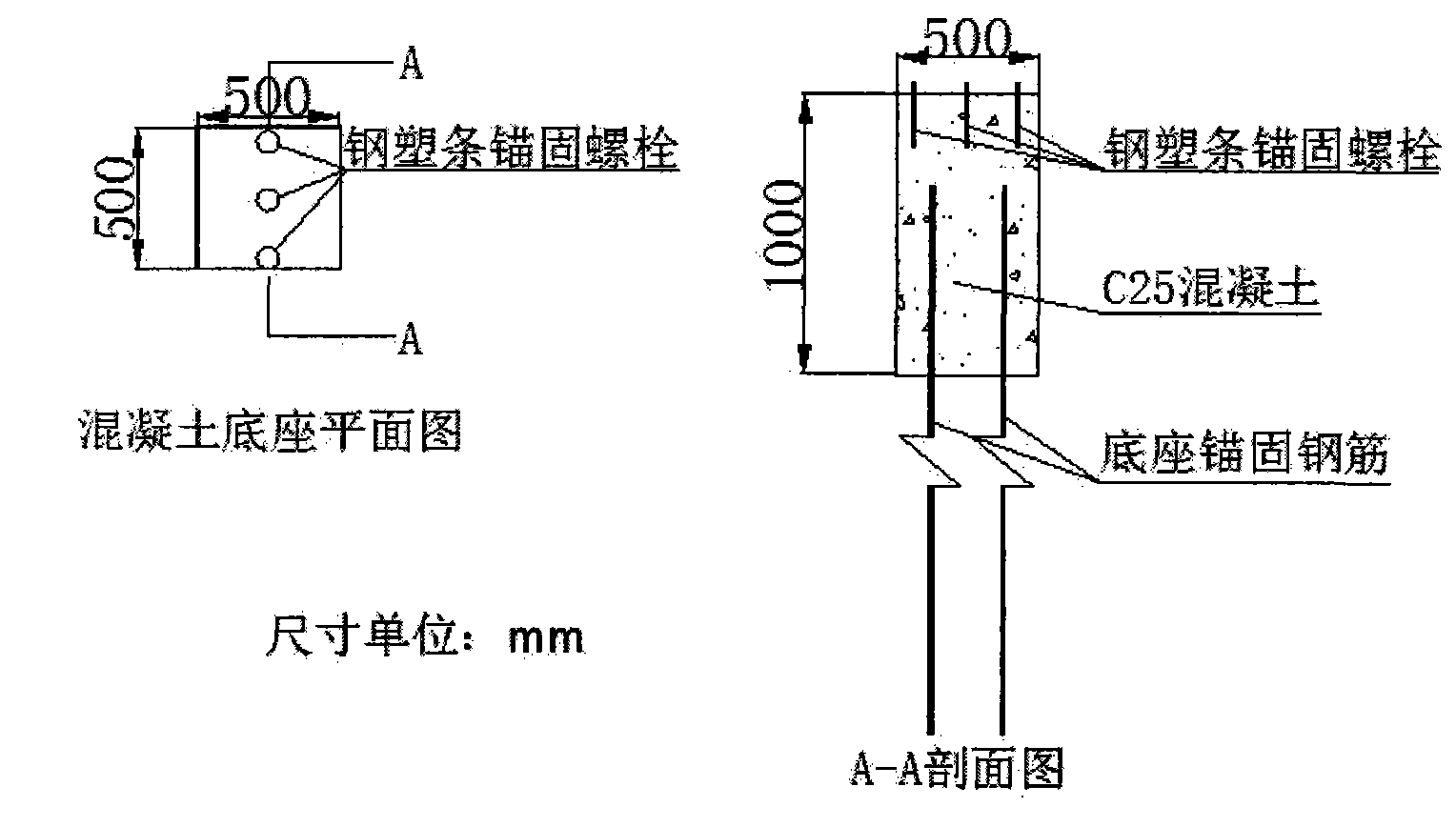
[0029] like figure 2 , image 3 , Figure 4 and Figure 5 As shown, the fiber grating measurement method for subsidence monitoring of embankment section includes the following steps:

[0030] 1) After cleaning the surface of the 100mm×2mm steel-plastic strip, arrange distributed strain sensing optical fiber and temperature compensation measurement sensing optical fiber on both sides of its center position. The strain sensing optical fiber and temperature compensation sensing optical fiber adopt structural glue The steel-plastic strips are firmly cemented, such as Figure 4 and Figure 5 ;

[0031] 2) After laying and cementing the sensing optical fiber on the steel-plastic strip, wrap the part where the sensing optical fiber is laid with double-layer geotextile, such as Figure 5 , anchoring holes are reserved at both ends, and one end leads to a fiber jumper connector to prepare for entering the distributed fiber optic measurement system;

[0032] 3) Complete the cons...

Embodiment 2

[0037] It is basically the same as in Example 1, except that other alloy bars meeting the strength and toughness requirements are used instead of steel-plastic bars.


PUM

PropertyMeasurementUnit
Ultimate tensile strengthaaaaaaaaaa
Depthaaaaaaaaaa
Bursting strengthaaaaaaaaaa

Abstract

The invention discloses an optical fiber grating measurement method for monitoring an embankment section settlement. The method comprises the following steps of: fixing steel-plastic strips or other alloy strips at two ends of a measured embankment section and adopting concrete fixed pedestals with ground anchors at the two ends; laying strain sensing optical fibers and temperature compensation sensing optical fibers on the surfaces of the steel-plastic strips or other alloy strips and fixedly gluing the sensing optical fibers on the steel-plastic strips or other alloy strips; wrapping the steel-plastic strips or other alloy strips glued with the sensing optical fibers with geotextiles; and mounting the steel-plastic strips or other alloy strips glued with the sensing optical fibers and wrapped and protected by the geotextiles on the monitored embankment section, and setting the two ends fixed on the monitored embankment section on the fixing pedestals. The method is simple, easy to implement, low in cost and suitable for measuring the settlement of the embankment section with any width and under any topographic conditions, can realize automatic measurement and has relatively high precision and accuracy shown by test results.

Description

technical field [0001] The invention relates to a method for measuring the settlement of an embankment section, in particular to an optical fiber grating measuring method for measuring the settlement of the embankment cross section. Background technique [0002] When roads and railways are built on soft soil foundations, under the action of the embankment load on the upper part, the soft soil foundation below it will have a large compression deformation. Because the embankment load is a strip load along the difference in the additional pressure distribution of the soft soil foundation under the embankment section, There are also differences in the settlement of the embankment in the cross section. At present, the settlement of embankment section is generally monitored by laying horizontal inclinometer pipes under the embankment, and using "little squirrels" to measure, such as figure 1 shown. The commonly known "little squirrel" is an instrument used to measure the settlem...

Claims


Application Information

Patent Timeline
IPC IPC(8): G01B11/16E01C3/00
Inventor 何宁丁勇何斌汪璋淳王国利钱亚俊赵宝林
Owner NANJING HYDRAULIC RES INST
Why Eureka
Try Eureka