Antenna structure

An antenna structure and coaxial line technology, applied in the direction of resonant antennas and resonant antenna components, can solve the problems of WLAN system performance degradation and cost waste

Inactive Publication Date: 2010-12-01
SHENXUN COMP KUNSHAN
View PDF5 Cites 3 Cited by
  • Summary
  • Abstract
  • Description
  • Claims
  • Application Information

AI Technical Summary

Problems solved by technology

[0008] In this embodiment, the length of the short-circuit arm 2 in the existing antenna structure is fixed, so the effective length of the vibrator 1 is also fixed, and the resonant frequency point of the antenna is also fixed. When the antenna is disturbed and a frequency deviation occurs It will cause the performance of the WLAN system to decline. At the same time, it often happens that the antennas made during product development fail to achieve the best results in the application, which leads to the re-production of antennas with different resonant frequency points, resulting in waste of cost.

Method used


Image

  • Antenna structure
  • Antenna structure
  • Antenna structure

Examples


Embodiment Construction

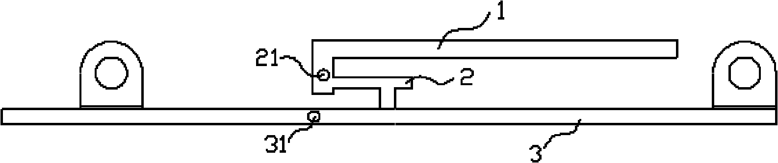
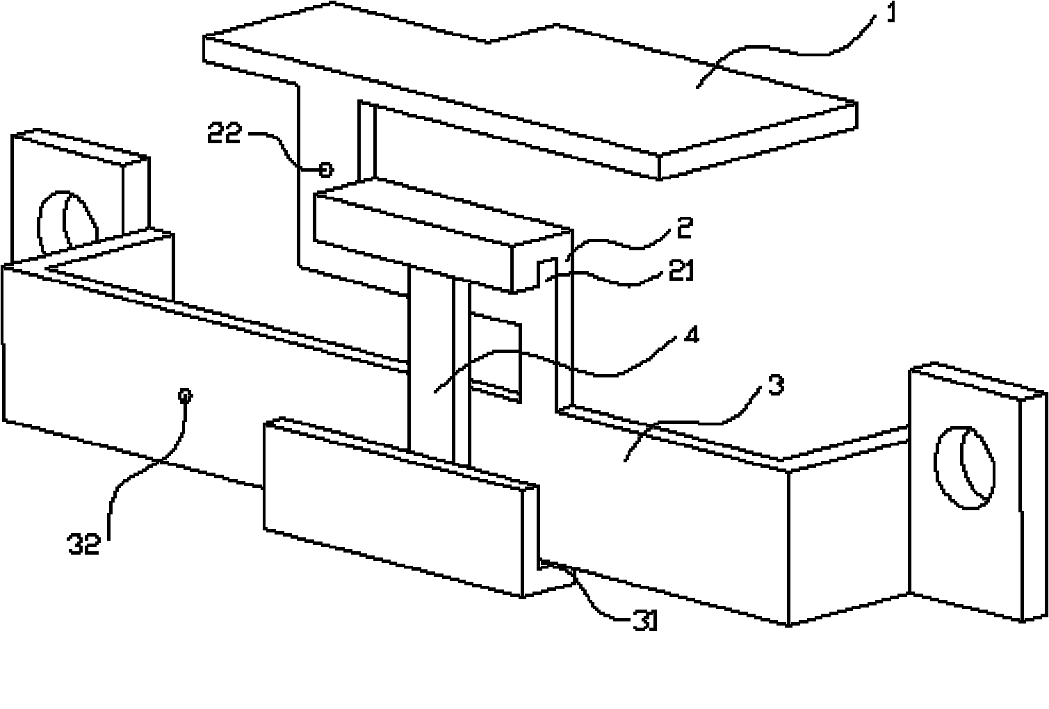
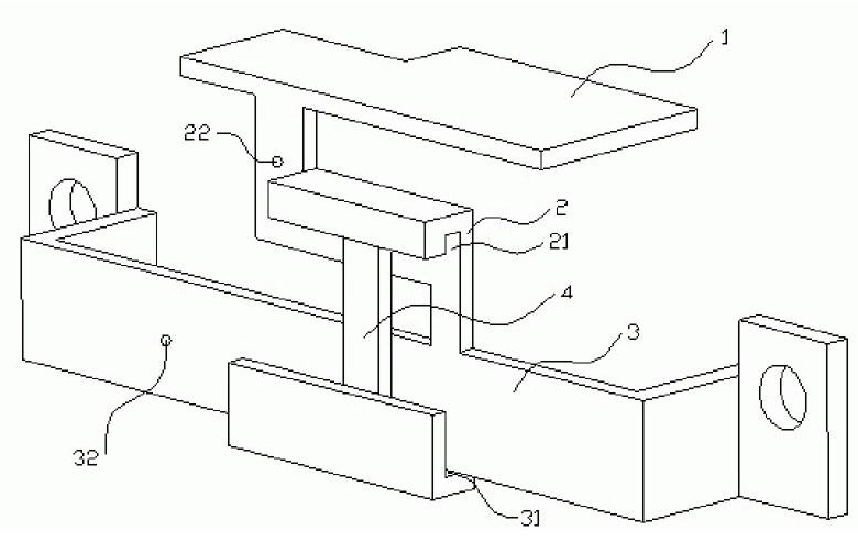
[0023] refer to figure 2 As shown, the antenna structure of the present invention includes:

[0024] a vibrator 1;

[0025] A short-circuit arm 2, one end of which is connected to the vibrator 1, a first sliding slot 21 is provided on the short-circuit arm, and a coaxial feed point 22 is also provided on the short-circuit arm 2;

[0026] A grounding metal sheet 3, one surface of which is connected to the other end of the short-circuit arm 2, the grounding metal sheet 3 is provided with

[0027] A second chute 31, and the ground metal sheet 3 is also provided with a coaxial line point 32;

[0028] A moving arm 4, which is arranged in the first chute 21 and the second chute 31 and slides in the two, the thickness of the moving arm 4 is equal to or slightly smaller than the first chute and 21 second chute The width of 31, so that the mobile arm 4 will not loosen in the first chute and the second chute 31 of 21.

[0029] In this embodiment, a moving arm 4 is added to the ante...


PUM


Abstract

The invention discloses an antenna structure. The antenna structure comprises a vibrator, a short-circuit arm, a grounded metal sheet and a movable arm, wherein one end of the short-circuit arm is connected with the vibrator, and the short-circuit arm is provided with a first chute; one surface of the grounded metal sheet is connected with the other end of the short-circuit arm, and the grounded metal sheet is provided with a second chute; and the movable arm is arranged in the first chute and the second chute and slides in the chutes. The effective length of the antenna vibrator can be adjusted by using the antenna structure, namely regulate a resonant frequency point used by an antenna so as to meet the requirements under different conditions; and antennas of different resonant frequency points does not need reproducing so as to save the cost.

Description

【Technical field】 [0001] The invention relates to an antenna structure, in particular to an antenna structure with adjustable dipole effective length. 【Background technique】 [0002] At present, the WLAN antenna structure used in the market is fixed. After the antenna is formed, the resonant frequency point of the antenna is also fixed. If the antenna is disturbed after the machine mechanism is installed, the frequency deviation of the antenna will cause the WLAN system. The performance is degraded. In this case, it is often necessary to replace the antenna or re-model and modify the antenna to achieve the best performance, which will inevitably increase the production cost. The existing antenna structure is as follows: [0003] figure 1 A schematic diagram showing the existing antenna structure. [0004] Such as figure 1 As shown, the existing antenna structure includes: [0005] a vibrator 1; [0006] A short-circuit arm 2, one end of which is connected to a surface ...

Claims


Application Information

Patent Timeline
Patent Type & Authority Applications(China)
IPC IPC(8): H01Q9/14
Inventor 沈细荣
Owner SHENXUN COMP KUNSHAN
Why Eureka
Try Eureka