
Imaging apparatus, imaging method, and program

An imaging device and imaging technology, applied in image communication, television, optics, etc.

Inactive Publication Date: 2010-12-01
SONY CORP
View PDF2 Cites 8 Cited by
  • Summary
  • Abstract
  • Description
  • Claims
  • Application Information

AI Technical Summary

Problems solved by technology

[0003]In the latter case, the shot may require a fast shutter speed

Method used


Image

  • Imaging apparatus, imaging method, and program
  • Imaging apparatus, imaging method, and program
  • Imaging apparatus, imaging method, and program

Examples


Embodiment Construction

[0044] The embodiments of the present invention will be described with reference to the drawings.

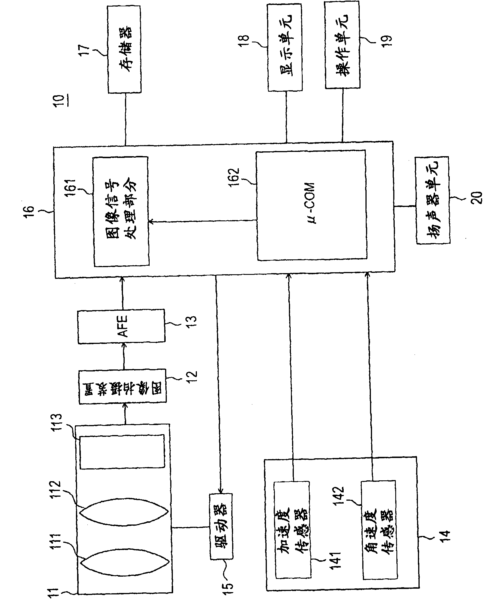
[0045] figure 1 It is a block diagram showing an example of the configuration of a camera device as an image processing device according to an embodiment of the present invention.

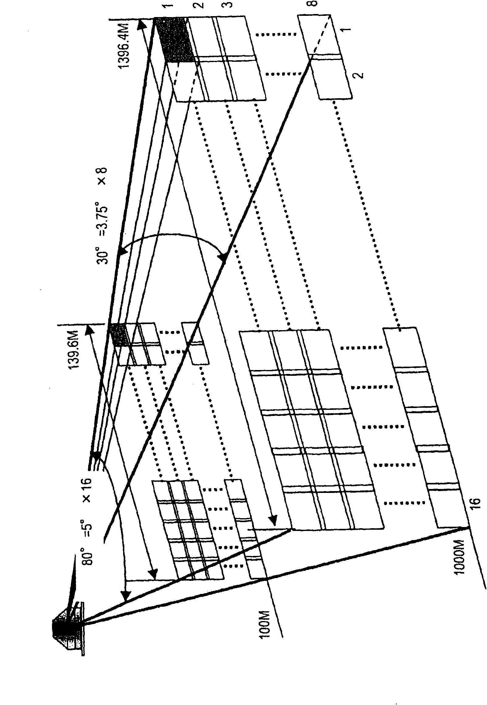
[0046] Such as figure 2 As shown, the camera device 10 of this embodiment is configured to obtain a large number of images by automatically or manually imaging multiple times in different directions from one point (in figure 2 The middle is 16×8=128).

[0047] The camera device 10 is configured to accurately synthesize a large number (for example, several thousand) images without wrinkles, thereby constituting a so-called panoramic image.

[0048] That is, the camera device 10 has a function of generating a panoramic image from an image imaged by a digital camera on which a solid-state imaging device such as a CMOS image sensor (CIS) is mounted, and the digital camera is vertically or horizontally mounted a...


PUM


Abstract

An imaging apparatus includes: an optical system having an optical axis changing element; an imaging device that images an object image through the optical system; an image signal processing section having a function of combining a plurality of imaged images into a combined image piece, the imaged images being obtained while the imaging apparatus is moved; and a controller that controls the optical axis changing element so that the optical axis is changed in a direction for negating the movement of the imaging apparatus, at least during periods when an electronic shutter of the imaging deviceis open, and that the optical axis returns to the vicinity of approximately the center of the movement of the imaging apparatus during periods when the electronic shutter is closed, wherein the controller performs the control of the optical axis with respect to a partial line in the central direction of the imaging device.

Description

Technical field [0001] The present invention relates to an imaging device, an imaging method, and a program having a function of synthesizing multiple images. Background technique [0002] In panoramic photography using a camcorder (camera built into a VTR), a digital camera, etc., when the camera's sweeping motion is stopped in each stage or a panoramic image is captured while having a continuous sweeping motion, In order to prevent the resulting image from blurring, it is necessary to sweep the camera at a low speed. [0003] In the latter case, shooting may require a high-speed shutter. [0004] In this regard, Japanese Patent No. 3928222 proposes a photographing method that can quickly sweep the camera while maintaining the image resolution. [0005] The technique used in this shooting method is a technique that can cancel out the resultant image by detecting the sweep direction and angular velocity of the camera and changing the optical axis at the same angular velocity in the o...

Claims


Application Information

Patent Timeline
Patent Type & Authority Applications(China)
IPC IPC(8): H04N5/225H04N5/232G02B27/00H04N5/262
CPCH04N5/23248H04N5/23238H04N5/23258H04N23/698H04N23/68H04N23/6812
Inventor 山下纪之藤田俊史
Owner SONY CORP
Learn More