Defogging system

a technology of defogging system and defogging plate, which is applied in the direction of vehicle maintenance, vehicle cleaning, transportation and packaging, etc., can solve the problems of thermal distortion and image distortion of imaging devi

Pending Publication Date: 2022-10-06
HONDA MOTOR CO LTD
View PDF0 Cites 0 Cited by
  • Summary
  • Abstract
  • Description
  • Claims
  • Application Information

AI Technical Summary

Benefits of technology

[0005]In view of the above background, an object of the present invention is to provide a defogging system that can effectively defog a window while effectively suppressing distortion of an image captured by an imaging device when a vehicle is traveling.

Problems solved by technology

In the abovementioned defogging system, when a heater of a direct heating type (that is, a heater in contact with the window) arranged inside a field of view of the imaging device heats the window, thermal distortion may occur in the window inside the field of view of the imaging device, which may distort an image captured by the imaging device.

Method used


Image

  • Defogging system
  • Defogging system
  • Defogging system

Examples


first embodiment

[0034]Hereinafter, a first embodiment of the present invention will be described with reference to FIGS. 1 to 5.

[0035]1>

[0036]First, a vehicle 1 according to the first embodiment of the present invention will be described with reference to FIGS. 1 to 4.

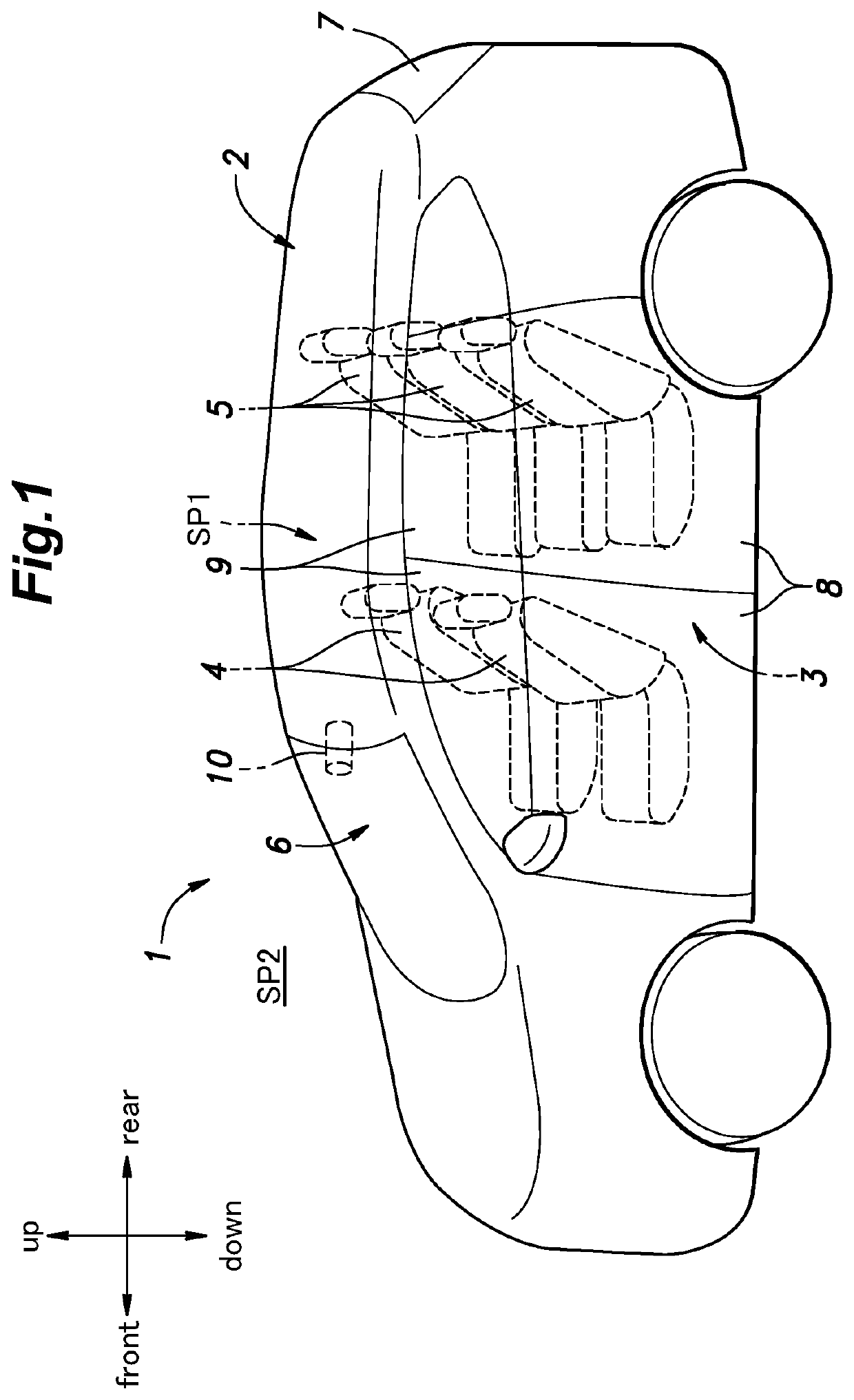
[0037]With reference to FIG. 1, the vehicle 1 according to the present embodiment consists of an automobile, the vehicle 1 includes a vehicle body 2 elongated in the front-and-rear direction. Inside the vehicle body 2, an inside space SP1 of the vehicle 1 (hereinafter simply referred to as “inside space SP1”) is formed. In a front-and-rear central portion of the inside space SP1, a vehicle cabin 3 for accommodating an occupant is provided. The vehicle cabin 3 is provided with, for example, a plurality of front seats 4 (a driver's seat and a passenger seat) and a plurality of rear seats 5 arranged behind the front seats 4. In the present embodiment, two rows of seats are provided in the front and rear. In another embodiment, only one r...

second embodiment

[0076]Next, a second embodiment of the present invention will be described with reference to FIG. 9. The contents other than the defogging control executed by the defogging control unit 54 are the same as those of the first embodiment. Accordingly, the description thereof will be omitted. Further, steps S11 to S15 of the defogging control according to the second embodiment are the same as steps S1 to S5 of the defogging control according to the first embodiment. Accordingly, the description thereof will be omitted.

[0077]In a case where the vehicle 1 is not stopped, that is, in a case where the vehicle 1 is traveling (step S14: No), the defogging control unit 54 determines whether the vehicle speed is equal to or higher than a prescribed reference speed (80 km / h in the present embodiment) (step S16). In another embodiment, the reference speed may be set to a speed other than 80 km / h.

[0078]In a case where the vehicle speed is equal to or higher than the reference speed (step S16: Yes)...

third embodiment

[0081]Next, a third embodiment of the present invention will be described with reference to FIG. 10. The contents other than the defogging control executed by the defogging control unit 54 are the same as those of the first embodiment. Accordingly, the description thereof will be omitted. Further, steps S21 to S26 of the defogging control according to the third embodiment are the same as steps S11 to S16 of the defogging control according to the second embodiment. Accordingly, the description thereof will be omitted.

[0082]In a case where the vehicle speed is equal to or higher than the reference speed (step S26: Yes), the defogging control unit 54 acquires the temperature of the second heater 29 (hereinafter referred to as “the heater temperature”) based on the detection result of the heater temperature sensor 45 (step S27).

[0083]Next, the defogging control unit 54 determines whether the heater temperature is equal to or lower than a prescribed threshold temperature (80° C. in the p...


PUM


Abstract

A defogging system includes: a vehicle speed sensor configured to detect a vehicle speed; a first heater arranged outside a field of view of an imaging device and configured to heat a window; a second heater arranged inside the field of view of the imaging device, arranged to be in contact with the window, and configured to heat the window; and a controller configured to control the first heater and the second heater. The controller is configured to determine whether the vehicle is stopped based on a detection result of the vehicle speed sensor, activate the first heater and the second heater in a case where a first condition is satisfied, the first condition including a condition that the vehicle is stopped, and activate only the first heater in a case where a second condition is satisfied, the second condition including a condition that the vehicle is traveling.

Description

TECHNICAL FIELD[0001]The present invention relates to a defogging system for defogging a window of a vehicle.BACKGROUND ART[0002]Conventionally, a vehicle includes an imaging device that captures an outside space of the vehicle from an inside space thereof through a window. Such a vehicle may include a defogging system for defogging the window. Such a defogging system includes, for example, a heater that heats the window and a controller that controls the heater.[0003]For example, JP2020-152324A discloses a mobile body including a monitoring device that monitors a surrounding environment of the mobile body through a transparent window, a heating device that heats a portion of the window inside a monitoring area of the monitoring device, an air conditioner that air-conditions an inside space of the mobile body, and a controller that controls the driving of the heating device and the air conditioner.[0004]In the abovementioned defogging system, when a heater of a direct heating type (...

Claims


Application Information

Patent Timeline
Patent Type & Authority Applications(United States)
IPC IPC(8): B60S1/02B60J1/00B60H1/00H05B3/84H05B1/02
CPCB60S1/026B60J1/002B60H1/00778H05B3/84H05B1/0236B60H1/00792H05B3/86B60J1/02H05B2203/014
Inventor KOCHI, TAKETONAKAJIMA, MASAKI
Owner HONDA MOTOR CO LTD
Why Eureka
Try Eureka