Quick stereo positioning method for video monitoring

A technology of stereo positioning and video monitoring, applied in TV, color TV, closed-circuit television system, etc., can solve the problems of inefficient and slow adjustment process, insufficient response in time, unacceptable, etc., to improve convenience and speed, and improve work efficiency Effect

Inactive Publication Date: 2010-12-01
SANLI VIDEO FREQUENCY SCI & TECH SHENZHEN
0 Cites 34 Cited by

AI-Extracted Technical Summary

Problems solved by technology

However, such complicated steps will inevitably lead to the inefficiency and slowness of the entire adjustment process. When an emergency occurs and it is necessary to quickly respond to and zoom in on a certain area of ​​the monitoring screen, the corresponding speed of the system will have many problems ...

Method used

This shows that the method that the present invention relates to can according to the relative position of target area in the whole CCD image area, automatically calculate the offset amount of target object and the step number that self attitude adjustment motor needs to move, self lens place After the zoom ratio needs to be adjusted, the user does not need t...

Abstract

The invention provides a quick stereo positioning method for video monitoring. The automatic positioning and adjusting control method suitable for a video monitoring system comprises the following steps: setting a positioning target, calculating the camera focal length, calculating the deviation angle of the target and a CCD center, calculating the number of moving steps of a cradle head motor, calculating zoom magnification, adjusting zoom and adjusting real-time positioning of the target. The method can automatically calculate the offset of the target and the number of steps of a self attitude adjusting motor required to move according to the relative position of the target area in the whole CCD image area, after the zoom magnification of the a lens is adjusted as required, a user can adjust the image without continuously depending on the actions of eyes of and a mouse, and the actions can be continuously and automatically controlled in position, thereby greatly improving the working efficiency of the monitoring system, and also improving the convenience and rapidness of using the monitoring system in a narrow bandwidth network environment for a user side.

Application Domain

Television system detailsColor television details +1

Technology Topic

Camera lensAutomatic control +8

Image

  • Quick stereo positioning method for video monitoring
  • Quick stereo positioning method for video monitoring
  • Quick stereo positioning method for video monitoring

Examples

  • Experimental program(1)

Example Embodiment

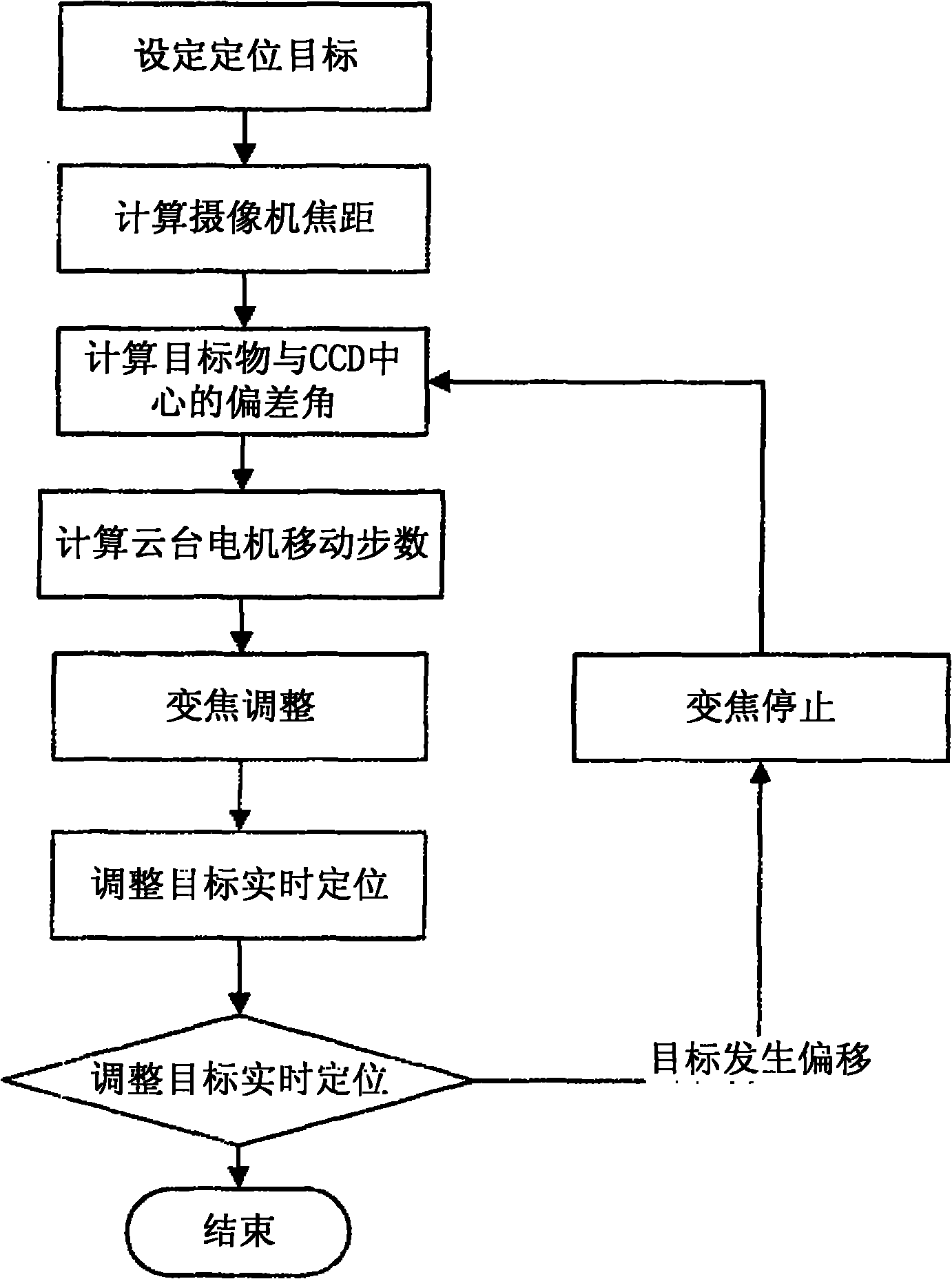
[0021] like figure 1 Shown, the present invention relates to a kind of video monitoring fast stereotaxic method, it comprises the step
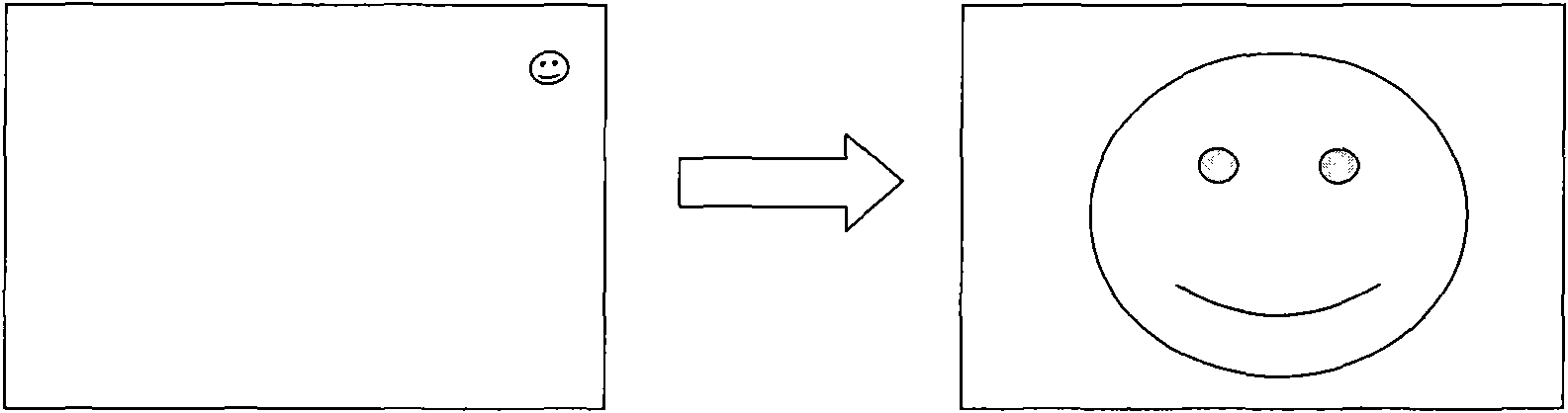
[0022] a) Set positioning goals, such as figure 2 , the user sets the target through the client, usually using the image window, by directly clicking with the mouse or selecting a frame; if it is a mouse click, the system determines that the click is the starting position of the target and calculates the coordinates of the target image position; if it is a frame selection, Then select the center point of the framed image as the starting position of the target and calculate the position coordinates of the target image;
[0023] b) Calculate the focal length of the camera, and determine the focal length according to the size of the CCD used in the camera and the vertical or horizontal angle of the camera lens;
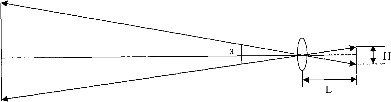
[0024] like image 3 , which is calculated according to the formula
[0025] Where L is the focal length of the camera to be calculated
[0026] H is the height or width of the CCD (usually known: such as common 1/4 "CCD)
[0027] a is the vertical or horizontal angle of the camera lens, and a takes the vertical or horizontal angle depending on whether H takes the height or width of the CCD in this formula, and the two correspond to the horizontal or vertical values ​​taken at the same time (known: the value of a is determined by The lens angle parameters corresponding to the zoom ratio of the camera provided by the camera manufacturer or obtained through testing are available).
[0028] c) Calculate the deviation angle between the target object and the CCD center, and determine the deviation angle between the target object and the CCD center according to the length of the line segment between the target object and the CCD center and the focal length of the camera;
[0029] The length of the centerline of the CCD, such as the size of the CCD used in common integrated cameras, is 1/4". 1/4" is the length of the diagonal line of the CCD, and the height of the target surface of the CCD is calculated according to the CCD aspect ratio of 4:3 It is 2.4mm, the width is 3.2mm and then its centerline length can be obtained.
[0030] like Figure 4 , the calculation of the deviation angle conforms to the formula
[0031] Where b is the deviation angle between the object to be calculated and the center of the CCD
[0032] x is the length of the target object and the central line segment of the CCD (in step a, after the target is selected, the coordinate information of the target image position can be calculated, and then combined with the difference between the pixel coordinate information of the point and the CCD center point pixel coordinate information can be obtained)
[0033] L is the camera focal length value calculated in the previous step
[0034] d) Calculate the number of moving steps of the pan-tilt motor, and obtain the number of moving steps of the pan-tilt motor according to the deviation angle between the target and the center of the CCD and the maximum number of steps allowed by the adjustment of the pan-tilt motor;
[0035] The calculation of the number of moving steps conforms to the formula
[0036] Where c is the moving steps of the gimbal motor to be determined
[0037] Smax is the maximum number of steps allowed for gimbal motor adjustment (known)
[0038] b is the deviation angle between the target object and the center of the CCD (known and calculated in the previous step).
[0039] e) Calculate the zoom adjustment ratio, and determine the zoom ratio of the image by calculating the ratio of the image selected by the mouse to the entire image in step a.
[0040] f) Zoom adjustment, adjust the zoom according to the calculated magnification, and at the same time detect whether there is an offset between the target and the center line of the CCD. If there is an offset, stop zooming and return to step c to re-determine the deviation angle, the number of moving steps of the pan and tilt and the zoom magnification.
[0041] g) Adjust the real-time positioning of the target, and detect whether there is an offset between the target and the CCD center line. If there is an offset, stop zooming, and return to step c to re-determine the deviation angle, the number of moving steps of the pan and tilt, and the zoom magnification.
[0042] It can be seen that the method involved in the present invention can automatically calculate the amount of offset of the target object and the number of steps required for the self-position adjustment motor to adjust the zoom of the self-lens according to the relative position of the target area in the entire CCD image area. After the magnification, the user does not need to continue to rely on human eyes and mouse actions to adjust the image, but can continuously and automatically control the action in place, which not only greatly improves the working efficiency of the monitoring system, but also improves the user's ability to use the monitoring system in a narrow bandwidth network environment. Convenience and speed.

PUM

no PUM

Description & Claims & Application Information

We can also present the details of the Description, Claims and Application information to help users get a comprehensive understanding of the technical details of the patent, such as background art, summary of invention, brief description of drawings, description of embodiments, and other original content. On the other hand, users can also determine the specific scope of protection of the technology through the list of claims; as well as understand the changes in the life cycle of the technology with the presentation of the patent timeline. Login to view more.

Similar technology patents

Automatic device for welding and detecting lithium battery

ActiveCN103904367AShorten the running distanceImprove work efficiency
Owner:DONGGUAN HONBRO LI BATTERY EQUIP TECH

Vacuum cleaner

InactiveCN103356140Aprevent liftingImprove work efficiency
Owner:SUZHOU HAAN TECH +1

Classification and recommendation of technical efficacy words

  • Improve work efficiency
  • Improve convenience and speed

Cooperation service platform facing different source data

InactiveCN101174957AImprove management level and qualityImprove work efficiency
Owner:NANJING UNIV OF FINANCE & ECONOMICS

Screw drilling tool, vertical drilling tool testing method and well inclination simulation testing equipment

InactiveCN111594144AReduced height requirementsImprove work efficiency
Owner:DEZHOU UNITED GASOLINEEUM MACHINERY

Method for intelligent automatic identification of transmission circuit parts

Owner:INFORMATION COMM COMPANY STATE GRID SHANDONG ELECTRIC POWER +2

Keyboard spill-proofing mechanism

ActiveUS7030330B2minimize manufacturing costimprove work efficiency
Owner:LITE ON SINGAPORE PTE LTD

Storage system for use information of mobile terminal and method

InactiveCN102316443ASave searching and downloadingImprove convenience and speed
Owner:ZTE CORP

Electric endosseous infusion system

ActiveCN110652347AImprove convenience and speedGuaranteed sterile safety
Owner:南昌大学第一附属医院

Network information output method of mobile terminal and mobile terminal

InactiveCN104065801AImprove convenience and speedreduce energy consumption
Owner:PHICOMM (SHANGHAI) CO LTD

Intelligent property management system

PendingCN114386924AImprove convenienceImprove convenience and speed
Owner:河北金锁安防工程股份有限公司

Data query method and device, electronic equipment and computer readable storage medium

PendingCN112988781AImprove convenience and speedImprove user experience
Owner:BEIJING KINGSOFT CLOUD NETWORK TECH CO LTD
Why Eureka
Try Eureka