Electronic parts installation apparatus

A technology for electronic component installation and electronic components, which is applied in the direction of electrical components, electrical components, etc., can solve problems such as the detour of the mounting head and the lengthening of the operation cycle time, and achieve the effects of suppressing errors, improving manufacturing efficiency, and suppressing bending or twisting

Active Publication Date: 2010-12-01
JUKI CORP
View PDF4 Cites 11 Cited by
  • Summary
  • Abstract
  • Description
  • Claims
  • Application Information

AI Technical Summary

Problems solved by technology

However, since the above-mentioned electronic component mounting apparatus must pass the mounting head above the image recogni

Method used


Image

  • Electronic parts installation apparatus
  • Electronic parts installation apparatus
  • Electronic parts installation apparatus

Examples


Example Embodiment

[0049] (Overall structure of the embodiment)

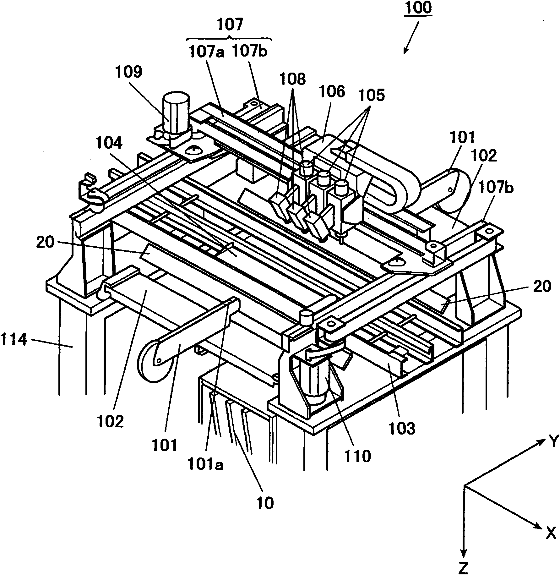
[0050] based on Figure 1 to Figure 11 Embodiments of the present invention will be described. Hereinafter, as shown in the figure, two directions orthogonal to each other on the horizontal plane are referred to as the X-axis direction (substrate conveyance direction) and the Y-axis direction (direction orthogonal to the substrate conveyance direction), respectively, and the direction perpendicular to these The vertical direction is the Z-axis direction. The electronic component mounting apparatus 100 mounts various electronic components on the substrate, such as figure 1 As shown, there are two sets of component supplying units consisting of a plurality of electronic component feeders 101 for supplying electronic components to be mounted, and a feeder storage box 102 for arranging and holding the plurality of electronic component feeders 101; A unit 103, which transports the substrate in the X-axis direction; a substrate hold...


PUM


Abstract

The present invention provides an electronic parts installation apparatus, capable of stably and accurately recognizing hold mode of the electronic parts. The apparatus includes a substrate holding part; a member supply part for supplying the electronic parts; a loading head having an adsorption nozzle; a loading head shifting mechanism capable of locating the loading head arbitrarily; a filming unit arranged on the loading head to film the electronic part absorbed by the adsorption nozzle; a filming reflection mirror extended between the member supply part and the substrate holding part and having only one reflecting plane; and an image processing device for judging the position and angle of the absorbed electronic part relative to the absorption nozzle according to the filming image of the electronic part obtained through reflection of the filming reflection mirror, wherein the reflecting plane of the filming reflection mirror is an inclined plane which adopts a bisecting line between a central line of the adsorption nozzle and the line of sight of the filming unit as its perpendicular line.

Description

technical field [0001] The present invention relates to an electronic component mounting device which confirms the holding state of an electronic component sucked by a suction nozzle and mounts it. Background technique [0002] Generally, an electronic component mounting apparatus has: a mounting head having a suction nozzle that receives electronic components from a feeder and transports them to a mounting position on a substrate; The electronic components held by the suction nozzle are photographed, and each time when mounting, the mounting head that holds the electronic component is passed directly above the camera to take an image. Through image processing of the captured image, the position of the electronic component relative to the center of the suction nozzle is obtained. The positional offset or the angle (inclination angle) around the center line of the suction nozzle is corrected based on these data, and then mounted. However, since the electronic component mount...

Claims


Application Information

Patent Timeline
IPC IPC(8): H05K13/04H05K13/08
Inventor 黑田洁
Owner JUKI CORP
Why Eureka
Try Eureka