Friction ring

A technology of friction rings and friction parts, which is applied in the field of friction rings, can solve the problems of wasted cost of friction plates and achieve the effect of reducing the burden

Inactive Publication Date: 2010-12-01
SCHAEFFLER TECH AG & CO KG
View PDF0 Cites 4 Cited by
  • Summary
  • Abstract
  • Description
  • Claims
  • Application Information

AI Technical Summary

Problems solved by technology

Applying friction linings by eg glu

Method used


Image

  • Friction ring
  • Friction ring
  • Friction ring

Examples


Embodiment Construction

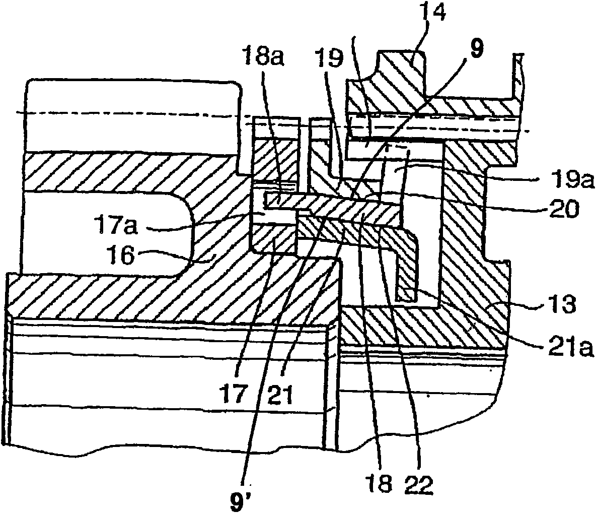
[0045] figure 1 By way of example, a synchronization device with an outer synchronizing ring 19 , a synchronizing intermediate ring 18 and an inner synchronizing ring 21 is shown. Synchronizing body 13 is secured by means of an internal toothing for a rotationally fixed arrangement on the transmission shaft. An escape wheel 16 is arranged in addition to the synchronizing body 13 . The clutch body 17 is connected to the escape wheel 16 , and the follower cam 18 a of the intermediate ring 18 engages in the recess 17 a of the clutch body 17 . The intermediate ring 18 forms a first friction pair 20 with the mating friction surface 9 of the outer synchronizing ring 19 as the mating cone 8, and forms a second friction pair 22 with the mating friction surface 9' of the inner synchronizing ring 21. The mating friction surfaces 9 and 9' are not reworked. The escape wheel 16 is connected to the synchronizing body 13 via a sliding sleeve 14 .

[0046] The inner edge 21 a of the inner...


PUM


Abstract

The invention relates to a friction ring (1) for a coupling, in particular a synchronizing mechanism of a motor vehicle transmission, having an annular body (2), wherein the annular body (2) has several recesses (3) and friction elements (4) are arranged in the recesses (3), the annular body (2) forms a cage which guides the friction elements (4) in the recesses (3), wherein the friction elements (4) are arranged slidably and/or torsionally in the recesses (3), wherein in the unstressed state first friction surfaces (27) protrude from the plane of the annular body (2) further than second friction surfaces (28) and when a preset stress is exceeded all friction surfaces (27, 28) can be brought into frictional contact with a friction partner.

Description

technical field [0001] The invention relates to a friction ring for a clutch or a synchronizing device, which has a ring body with a plurality of recesses, wherein friction elements are arranged in the recesses. Background technique [0002] Friction rings of motor vehicle transmissions are usually formed by a cylindrical or conical ring having a friction surface on the inner or outer surface. If the friction ring has friction surfaces on both outer surfaces, it is also referred to as an intermediate ring. During the clutching process, the friction surface of the intermediate ring remains connected in a friction fit manner on the outer casing to the friction surface formed on the outer mating cone. At the same time, the friction surface formed on the inner cover surface of the intermediate ring maintains a friction fit with the friction surface of the inner fitting cone. [0003] In the synchronizing device, the outer synchronizing ring is positively connected to the synch...

Claims


Application Information

Patent Timeline
IPC IPC(8): F16D23/06
CPCF16D23/06F16D2023/0681F16D23/025
Inventor 托马斯·卡拉斯蒂尔·沙夫帕斯卡尔·考特斯京特·普里维特雷纳·许贝尔拉斐尔·维特曼
Owner SCHAEFFLER TECH AG & CO KG
Why Eureka
Try Eureka