Current sensor with laminated magnetic core

A current sensor and magnetic core technology, applied in the direction of magnetic core/yoke, voltage/current isolation, transformer/inductor core, etc., can solve problems such as change, unresponsive magnetic induction, and air gap size change

Active Publication Date: 2010-12-01
莱姆电子(中国)有限公司
View PDF1 Cites 16 Cited by
  • Summary
  • Abstract
  • Description
  • Claims
  • Application Information

AI Technical Summary

Problems solved by technology

Over time, these stresses and the aging of materials and components can lead to inaccurate current measurements
[0004] In conventional laminated cores, shock, vibration and thermal stress can lead to degradation of the welds that hold the stacked sheets

Method used


Image

  • Current sensor with laminated magnetic core
  • Current sensor with laminated magnetic core
  • Current sensor with laminated magnetic core

Examples


Example Embodiment

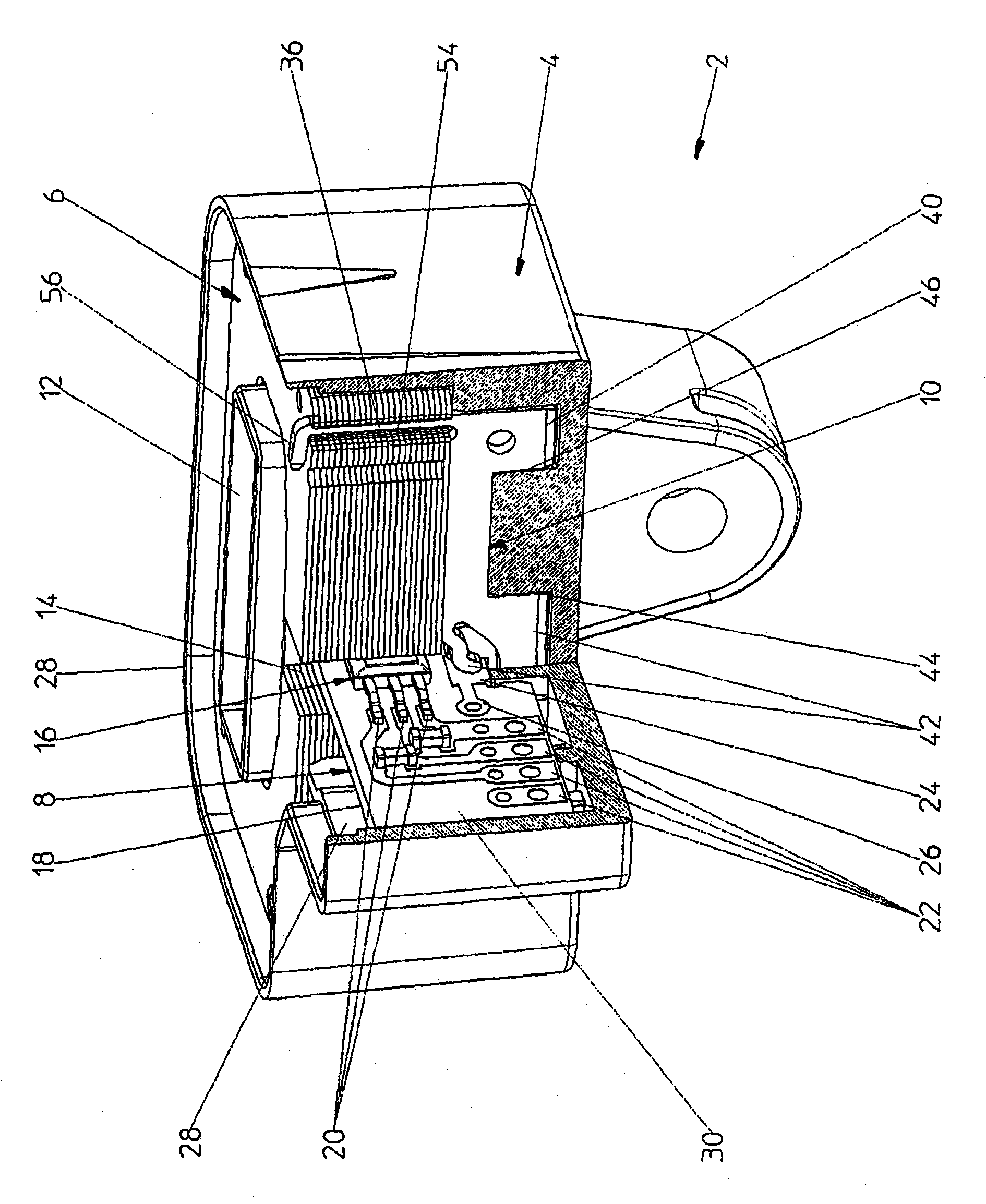
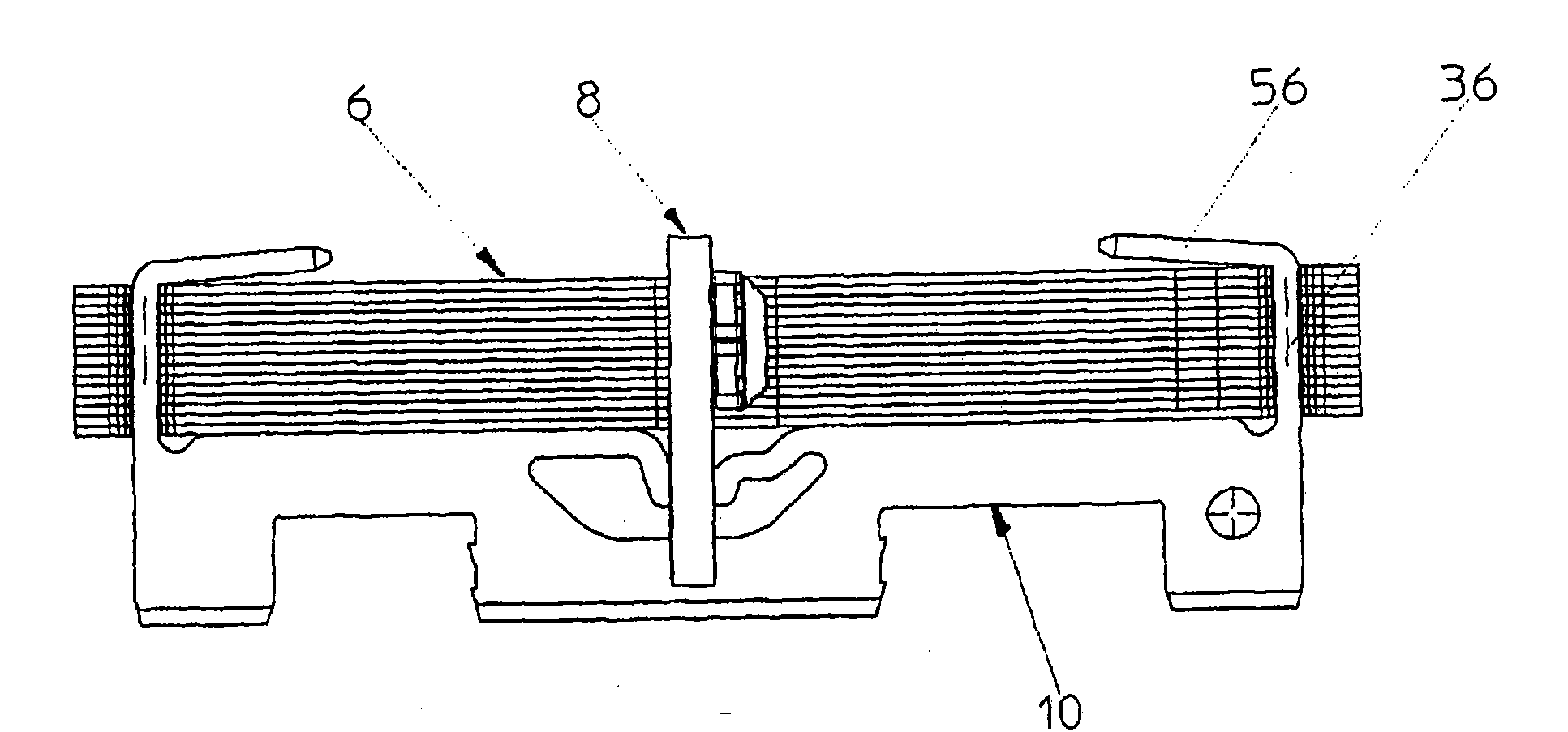
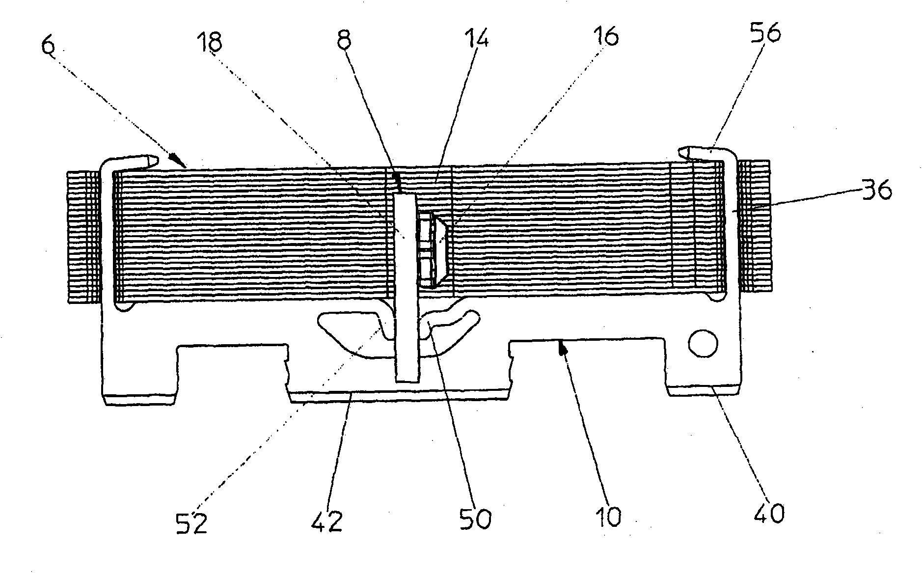
[0021] Referring to the drawings, the current sensor 2 includes a housing 4, a magnetic core 6, a magnetic field detector 8 and a mounting element 10.

[0022] The magnetic core is composed of a stack of sheets of high permeability materials known in the art. The magnetic core surrounds the opening 12 through which a main conductor 5 (not shown) through which the current to be measured flows. The magnetic core 6 has an air gap 14, which in the illustrated embodiment passes completely through the magnetic core. However, within the scope of the present invention, the air gap may also be a partial air gap, whereby the magnetic core forms a closed or substantially closed magnetic circuit. Depending on the intensity of the current to be measured, the height H of the stacked sheets constituting the magnetic core can be changed, such as Figure 2a with 2b Shown. For cost and weight reasons, it is advantageous to adjust the height of the magnetic core according to the application and t...


PUM


Abstract

An electrical current sensor (2) comprising a magnetic core (6) with an air gap (14), a magnetic field detector (8) positioned at least partially in the air gap, and a conductive mounting element (10). The mounting element comprises at least first and second fixing extensions (56) extending between opposed outer faces of the magnetic circuit, and a bridge portion (34) interconnecting the fixing extensions and spanning across the air gap. The bridge portion comprises an electrical terminal (42) in electrical contact with a grounding pad (24) of the magnetic field detector.

Description

technical field [0001] The invention relates to a current sensor having a magnetic field detector located in the air gap of a laminated magnetic core. Background technique [0002] Current sensors having a laminated magnetic core and a magnetic field detector located in the air gap of the core are well known and widely used. The magnetic core is placed around the conductor through which the current to be measured flows. The magnetic induction generated by the current is measured by a magnetic field detector located in the air gap of the core. To reduce eddy currents, many magnetic cores are typically constructed of multiple stacked sheets of a material with high magnetic permeability, such as a soft iron-nickel alloy. The stacked sheets making up the core are usually joined together by pressing and welding operations at specific points around the core. One of the commonly used magnetic field detectors is the Hall sensor, which is in the form of an integrated circuit (ASIC...

Claims


Application Information

Patent Timeline
IPC IPC(8): G01R15/20H01F27/26
CPCG01R15/207H01F3/14H01F27/26H01F27/402
Inventor A·拉贝
Owner 莱姆电子(中国)有限公司
Why Eureka
Try Eureka