Thin film planar solar concentrator/collector

A solar energy and light guide technology, applied in solar collectors, solar thermal energy, solar thermal power generation, etc., can solve problems such as bulky, bulky and complex systems

Inactive Publication Date: 2010-12-01
IDC LLC
View PDF0 Cites 24 Cited by
  • Summary
  • Abstract
  • Description
  • Claims
  • Application Information

AI Technical Summary

Problems solved by technology

These systems are complex, often bulky and bulky

Method used


Image

  • Thin film planar solar concentrator/collector
  • Thin film planar solar concentrator/collector
  • Thin film planar solar concentrator/collector

Examples


Embodiment Construction

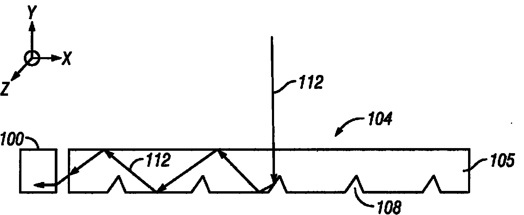
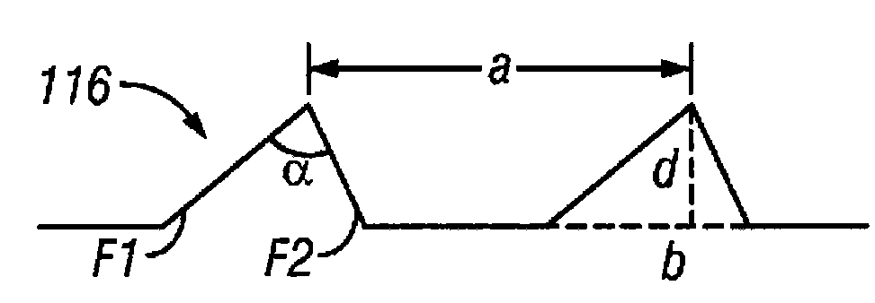
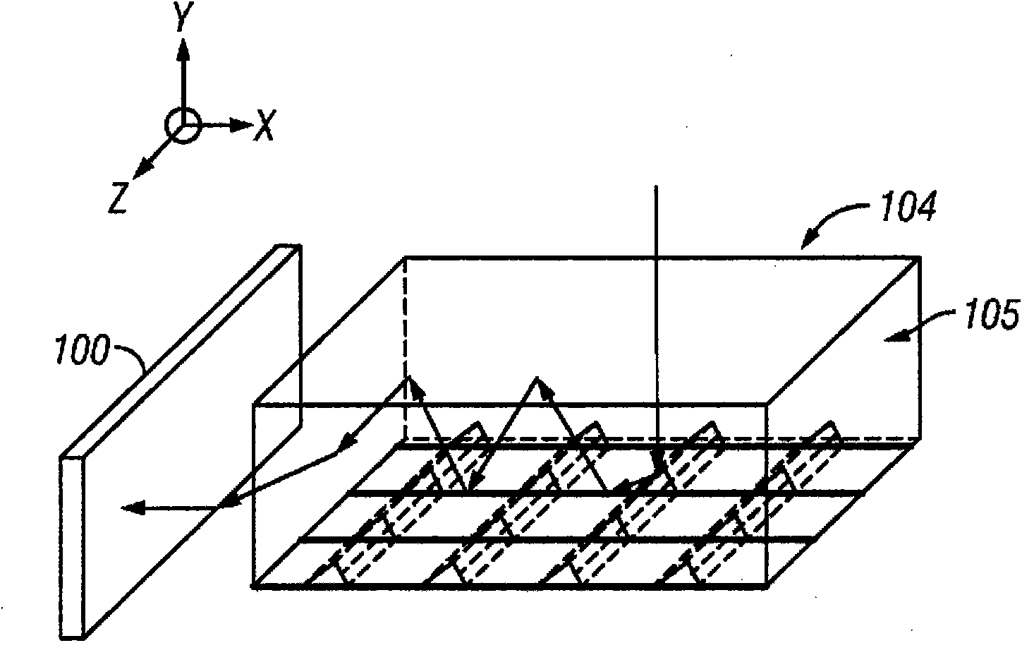
[0044] The following detailed description is directed to some specific embodiments of the present invention. However, the invention can be embodied in many different ways. As will be apparent from the description below, the embodiments may be implemented in any device configured to collect, trap, and concentrate radiation from a source. More particularly, the present invention contemplates that the embodiments described herein may be implemented in or associated with a wide variety of applications, such as providing power to residential and commercial property, powering, for example, laptop Electronic devices such as computers, PDAs, watches, calculators, cellular phones, camcorders, cameras and camcorders, mp3 players, etc. provide power. Additionally, embodiments described herein may be used in wearable power-generating clothing, shoes, and accessories. Some of the embodiments described herein can be used to charge car batteries, navigation instruments, and pump water. Em...


PUM

PropertyMeasurementUnit
widthaaaaaaaaaa
depthaaaaaaaaaa
conversion efficiencyaaaaaaaaaa

Abstract

In various embodiments described herein, a device comprising a light guiding layer (204, 212) optically coupled to a photocell (200) is described. A plurality of surface features (208, 216) are formed on one of the surfaces of the light guiding layer (204, 212). The surface features (208, 216) can comprise facets that are angled with respect to each other. Light (220, 224) incident on the surface of the light guide is redirected by the surface features and guided through the light guide (204, 212) by multiple total internal reflections. The guided light is directed towards a photocell (200).

Description

technical field [0001] The present invention relates to the field of light collectors and concentrators, and more particularly to the use of microstructured films to collect and concentrate solar radiation. [0002] This application asserts U.S. Patent Application No. 11 / 941,851, filed November 16, 2007, entitled "THIN FILM SOLAR CONCENTRATOR / COLLECTOR" (Attorney Docket No. QMRC.001A ), said patent application is hereby expressly incorporated herein by reference in its entirety. Background technique [0003] Solar energy is a renewable energy source that can be converted into other forms of energy such as heat and electricity. The main disadvantages of using solar energy as a reliable renewable energy source are the inefficiency of converting light energy into heat or electricity and the variation of solar energy depending on the time of day and month of the year. [0004] Photovoltaic (PV) cells, which are based on the principle of converting light energy into electrical ...

Claims


Application Information

Patent Timeline
Patent Type & Authority Applications(China)
IPC IPC(8): H01L31/052G02B6/00F24S23/00
CPCY02B10/20F24J2/067Y02E10/40Y02E10/52F24J2002/003G02B6/0038H01L31/0522G02B6/0036G02B6/0076F24S23/12F24S2023/88H01L31/0547Y10T29/49002
Inventor 鲁塞尔·韦恩·格尔科徐刚马克·莫里斯·米尼亚尔约恩·比塔马雷克·米恩克王莱乔纳森·查尔斯·格里菲斯马尼什·科塔里卡斯拉·哈泽尼
Owner IDC LLC
Why Eureka
Try Eureka