Self-locking bottom opening trough

A trough and self-locking technology, applied in the field of metallurgy, achieves the effect of simple structure and reliable operation

Inactive Publication Date: 2010-12-08
CISDI ENG CO LTD
View PDF6 Cites 20 Cited by
  • Summary
  • Abstract
  • Description
  • Claims
  • Application Information

AI Technical Summary

Problems solved by technology

Although the device can automatically unload the material, it still needs to use the external force of the hydraulic push-pull rod to open and close the trough.

Method used


Image

  • Self-locking bottom opening trough
  • Self-locking bottom opening trough
  • Self-locking bottom opening trough

Examples


Embodiment

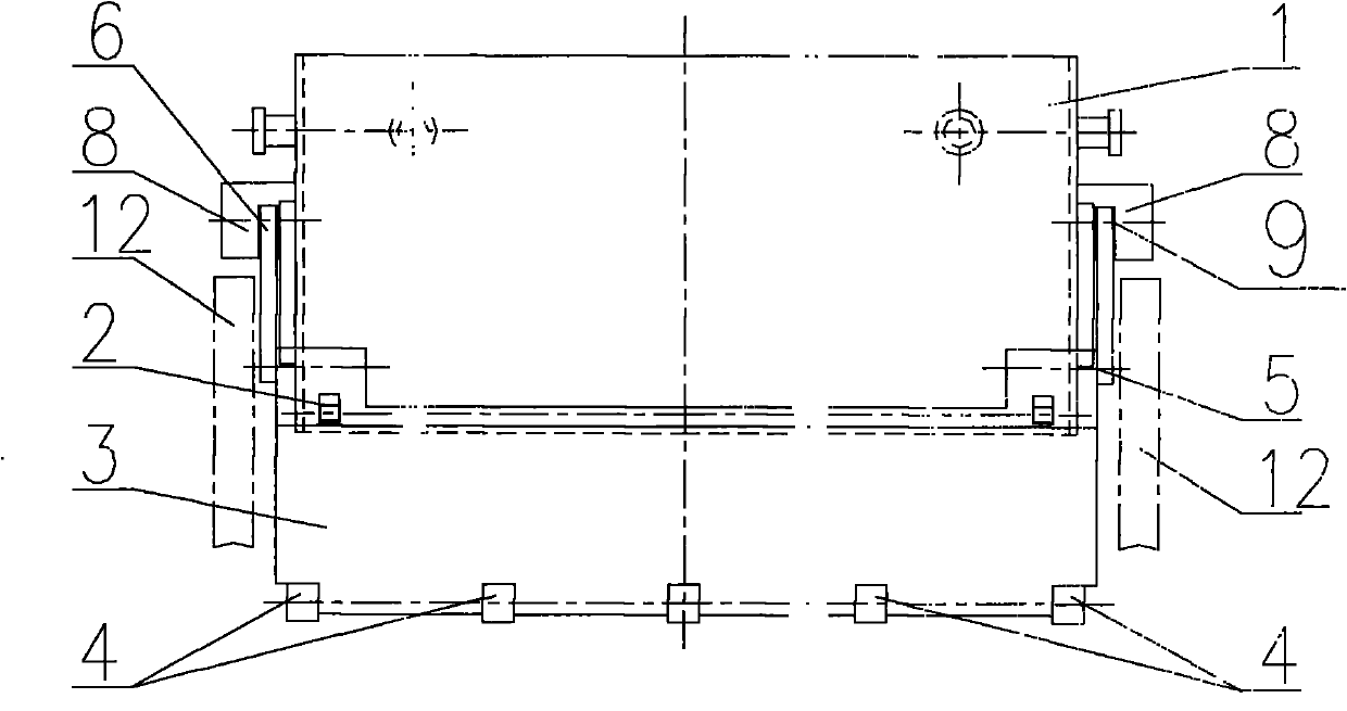
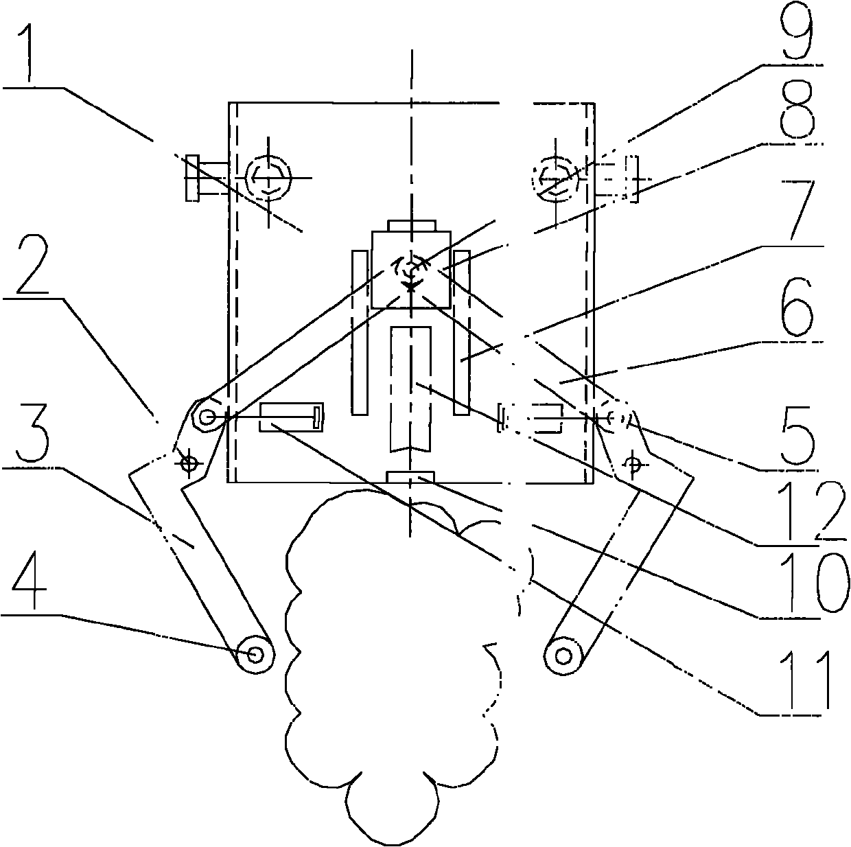
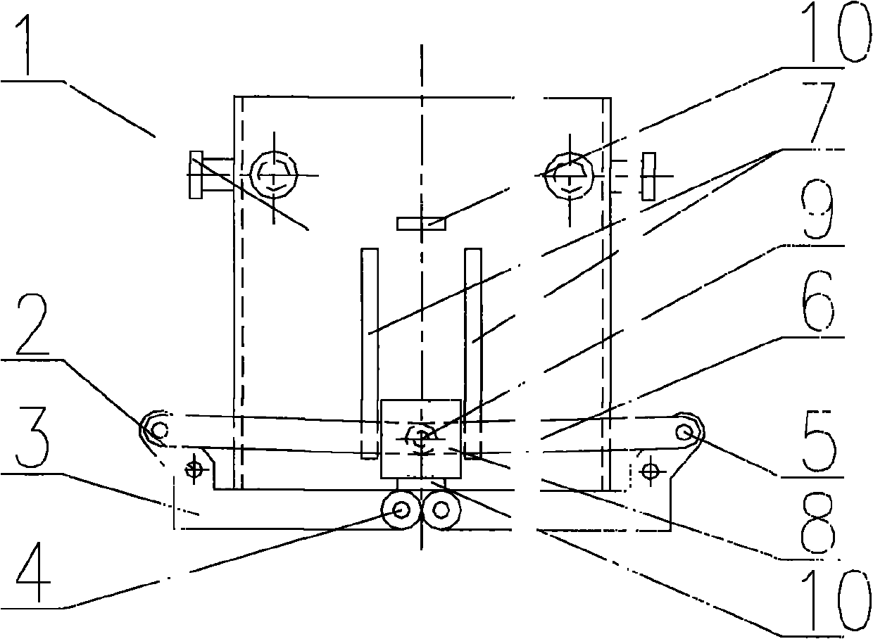
[0019] An embodiment, a self-locking bottom opening chute, including a chute 1, two swing doors 3 are arranged at the bottom of the chute 1, and the swing door 3 is connected to the chute 1 through the hinge axis A2 and can swing around the hinge axis A2 , the two sides of the trough 1 are provided with a weight slider 8, the weight slider 8 is connected with the swing door 3 through the connecting rod 6 and an external support 12 is arranged below;

[0020] The connecting rod 6 is hinged with the swing door 3 through the hinge shaft B5, and is hinged with the weight slider 8 through the hinge shaft C9;

[0021] A guide rail 7 is provided on the side wall of the trough 1, and the weight slider 8 moves up and down along the guide rail 7;

[0022] A limit block 10 is provided below the guide rail 7;

[0023] Dampers 11 are arranged on both sides of the trough 1;

[0024] The lower edge of the swing door 3 is provided with a roller 4;

[0025] The trough 1 is a cube, and can a...


PUM


Abstract

The invention discloses a self-locking bottom opening trough, which comprises a trough and is characterized in that: the bottom of the trough is provided with two swing doors which are connected with the trough by a hinged shaft A and can swing around the hinged shaft A; weight sliders are arranged on the two sides of the trough and connected with the swing doors through connecting rods; and external supports are arranged below the weight sliders. When the trough falls, the weight sliders rise relative to the trough with the support of the external supports; the connecting rods drive the swing doors to swing around the hinged shaft A and open; and thus, feed in the trough falls automatically. In the invention, the automatic discharge of the bottom opening trough and the automatic closing and locking of the swing doors are realized by the self-locking function generated by the weight sliders and the swing doors and the gravity of the trough, and the falling speed of the materials can be controlled by a damper. The self-locking bottom opening trough has a simple structure and works reliably.

Description

technical field [0001] The invention belongs to the technical field of metallurgy and relates to a self-locking bottom opening trough, which is also suitable for transportation, mine transportation, mechanical transportation, logistics transportation and other industries. Background technique [0002] In the metallurgical industry, common rapid transport equipment includes electric furnace bottom open material baskets, connecting rod lifting bottom open material tanks, etc. The bottom-opening material basket of the electric furnace is circular, and the bottom-opening door adopts a swing method. The opening of the bottom swing door must have external traction; There are limitations in releasing the lift link. [0003] The patent No. 200920106544.0 discloses an openable and closable clamshell type chute device, which includes a chute, a jacking piece and a tipping chute device, the chute is composed of two and a half chute and can be Rotating around the pin shaft, the jackin...

Claims


Application Information

Patent Timeline
Patent Type & Authority Applications(China)
IPC IPC(8): B65D88/28
Inventor 黄其明刘向东行开新
Owner CISDI ENG CO LTD
Why Eureka
Try Eureka