Supporting roller device for tube type belt conveyor

A belt conveyor and idler technology, applied in the direction of rollers, conveyors, conveyor objects, etc., can solve the problems of easy damage, unevenness, and reduced service life of partitions, and achieve improved stability, prolonged contact time, and improved durability. uniform force effect

Inactive Publication Date: 2010-12-08
SHANGHAI KEDA HEAVY IND GROUP
View PDF5 Cites 1 Cited by
  • Summary
  • Abstract
  • Description
  • Claims
  • Application Information

AI Technical Summary

Problems solved by technology

[0004] Since all the rollers are located on the same side, the force on the partition will be on the same side, which is very uneven
And because the tape always passes through the partition from one direction when it is running, it will exert a large shear force on the partition. The superposition of the two factors will cause the partition to be easily damaged and the service life will be reduced.

Method used


Image

  • Supporting roller device for tube type belt conveyor
  • Supporting roller device for tube type belt conveyor
  • Supporting roller device for tube type belt conveyor

Examples


Embodiment 1

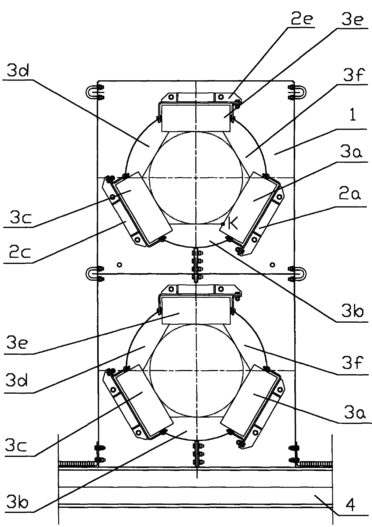
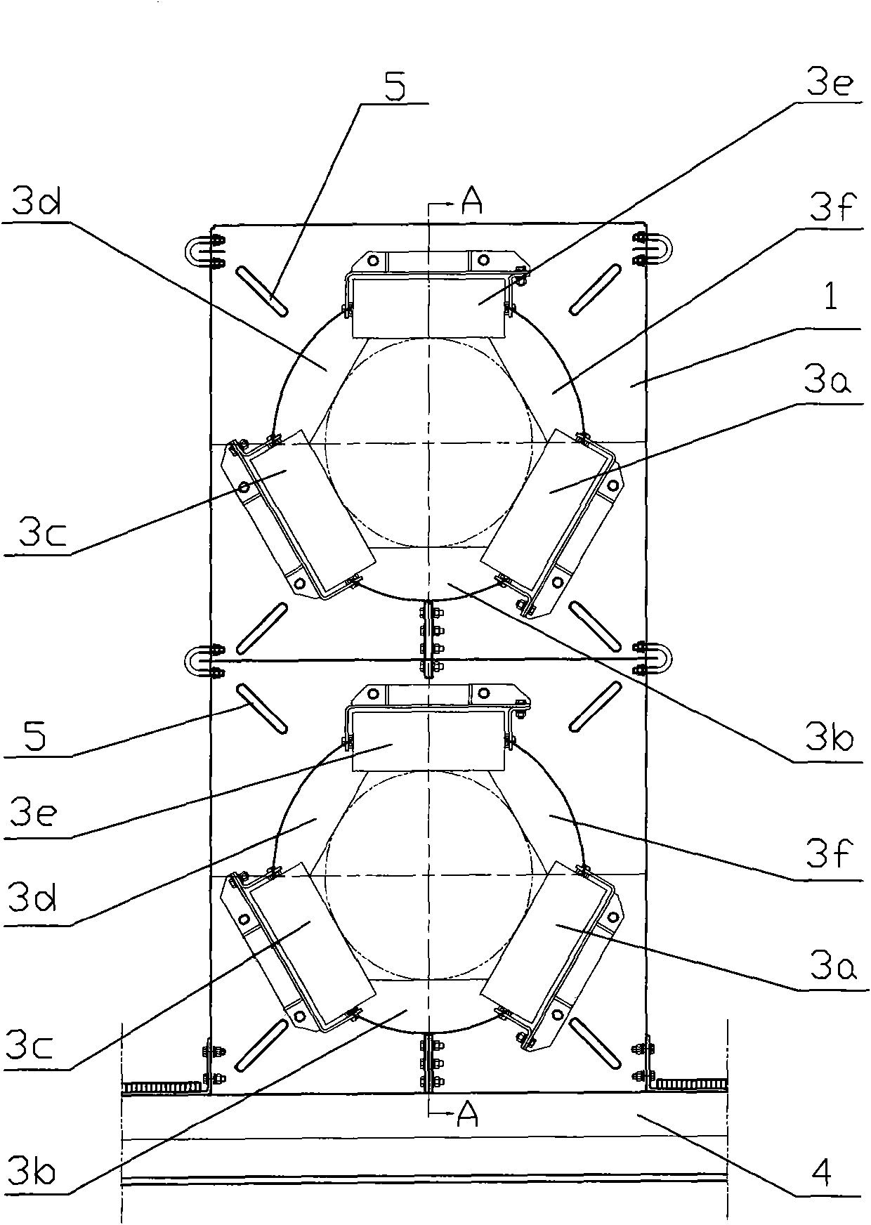
[0026] Attached figure 1 The front view of the roller device of this embodiment, attached figure 2 Is the rear view of the roller device, attached image 3 In order to omit part of the unpainted right side view of the roller frame.

[0027] As attached Figure 1~3 As shown, the supporting roller device in this embodiment is composed of a partition plate 1, a supporting roller frame 2, and a supporting roller 3. Among them, the partition 1 is fixedly installed on the frame 4 of the tubular belt conveyor, and the idler 3 is supported by the roller frame 2 and fixedly installed on the partition 1. In this embodiment, there are 6 rollers in a group, so in the figure, a, b, c, d, e, f are used to represent the 6 rollers 3 in the same group, and the corresponding roller rack 2 . Any two adjacent rollers 3, such as rollers 3a and 3b, are respectively located on both sides of the partition 1, so that both sides of the partition 1 are uniformly stressed and the rigidity is improved.

[...

Embodiment 2

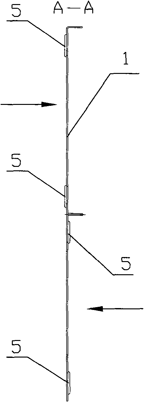
[0031] As attached Figure 4 And Figure 5 As shown, the difference between Embodiment 2 and Embodiment 1 is that four strip-shaped grooves 5 are pressed on each partition 1 to further improve the rigidity of the partition 1.

[0032] Since the adhesive tape exerts a large shear force on the partition 1 during operation, the partition 1 is likely to bend in the running direction of the tape. Therefore, a plurality of grooves 5 are pressed on the partition 1 in a direction opposite to the running direction of the tape.

[0033] These grooves 5 extend along the radial direction of the cylinder enclosed by the tape. If the partition 1 is bent due to the shearing force of the tape running for a long time, the creases are mostly around the circumference of the tape tube. Therefore, the groove 5 extending in the radial direction is perpendicular to the direction in which bending may occur, thereby resisting bending, improving the rigidity, and prolonging the service life of the separato...


PUM


Abstract

The invention discloses a supporting roller device for a tube type belt conveyor, comprising a partition board vertical to the running direction of a belt, a plurality of supporting roller brackets fixedly arranged on the surface of the partition board, and a plurality of supporting rollers respectively fixedly arranged on the supporting roller brackets. The central line of the rotating shafts of the supporting rollers form a regular polygon; the number of the supporting rollers is even; and adjacent two supporting rollers are respectively positioned at both sides of the partition board. Because adjacent two supporting rollers are arranged at both sides of the partition board, even force is applied on the partition board which is therefore not bent because of long-term stress on one side. The contact time between six supporting rollers arranged at both sides of the partition board and the belt is prolonged to improve the operation stability of the belt.

Description

Technical field [0001] The invention relates to a material conveying device, in particular to a roller device for a tube type belt conveyor. Background technique [0002] The tube belt conveyor is a continuous transport machine that places materials in a tube-shaped tape, and is carried and transported by the tape. The tape is given proper tension by the tensioning device, and runs by friction with the drive roller to form a closed loop. In this closed loop, the upper and lower branches of the tape are supported by idlers. [0003] There are usually 6 rollers in a group of tube type belt conveyors. The 6 rollers are arranged in a regular hexagon to surround the tape. And, the 6 idlers are all located on the same side of the partition used to fix the idlers. [0004] Since all the rollers are on the same side, the force that the partition bears is on the same side, which is very uneven. And because the tape always passes through the partition from one direction during operation, a...

Claims


Application Information

Patent Timeline
Patent Type & Authority Applications(China)
IPC IPC(8): B65G15/60B65G39/12
Inventor 刘新
Owner SHANGHAI KEDA HEAVY IND GROUP
Why Eureka
Try Eureka