Automatic gear clearance elimination mechanism

An automatic and anti-backlash technology, applied in the direction of belts/chains/gears, mechanical equipment, components with teeth, etc., can solve problems such as adjustment difficulties, space and structure restrictions, and achieve stable and reliable work and convenient installation and use.

Inactive Publication Date: 2010-12-08
XIANGYANG BOYA PRECISION IND EQUIP
View PDF7 Cites 14 Cited by
  • Summary
  • Abstract
  • Description
  • Claims
  • Application Information

AI Technical Summary

Problems solved by technology

[0007] The principle of the anti-backlash structure of the above 2-4 gears is roughly the same, but after the gears are worn out, the driving and driven gears need to be loo

Method used


Image

  • Automatic gear clearance elimination mechanism
  • Automatic gear clearance elimination mechanism
  • Automatic gear clearance elimination mechanism

Examples


Embodiment Construction

[0014] specific implementation plan

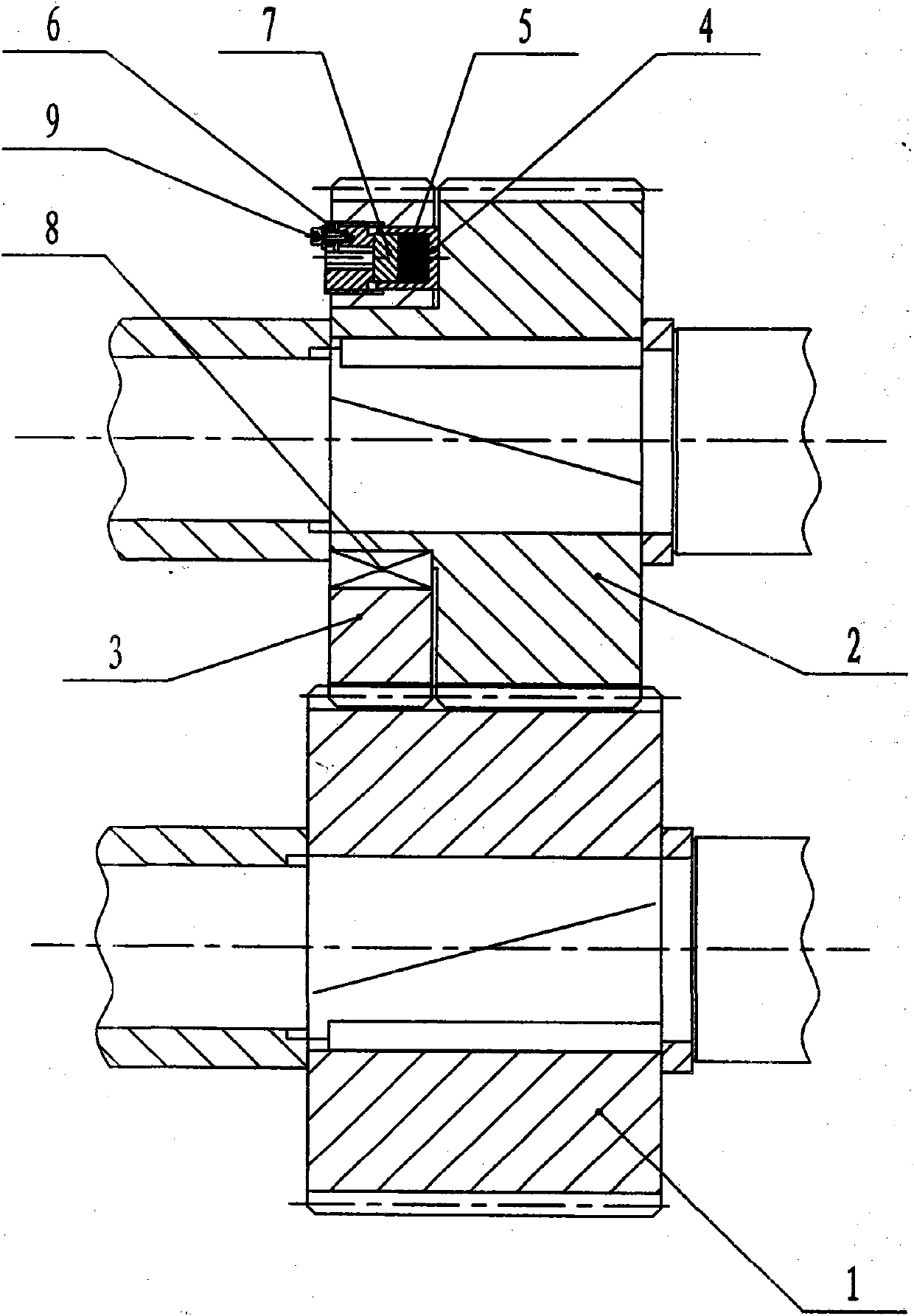
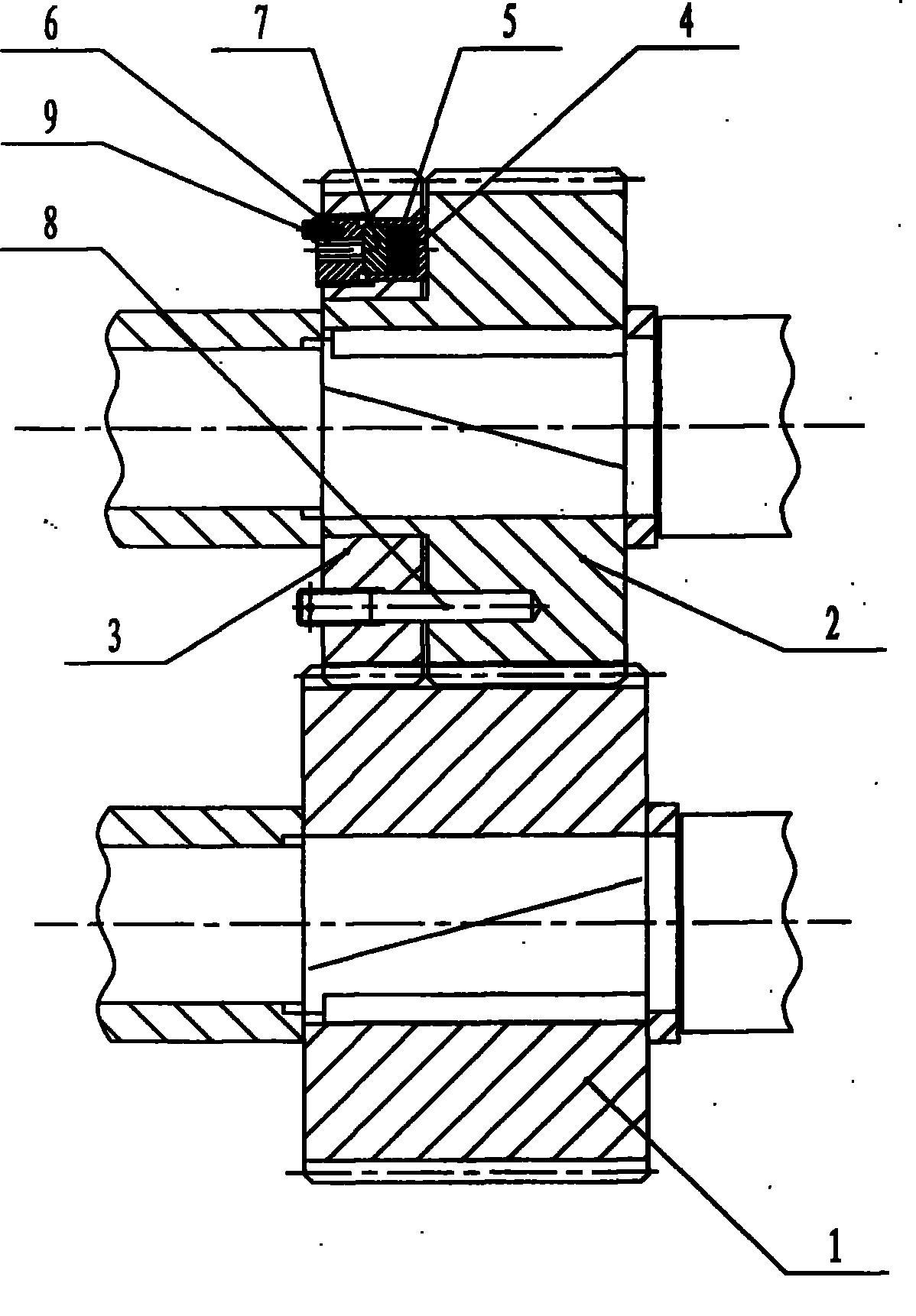
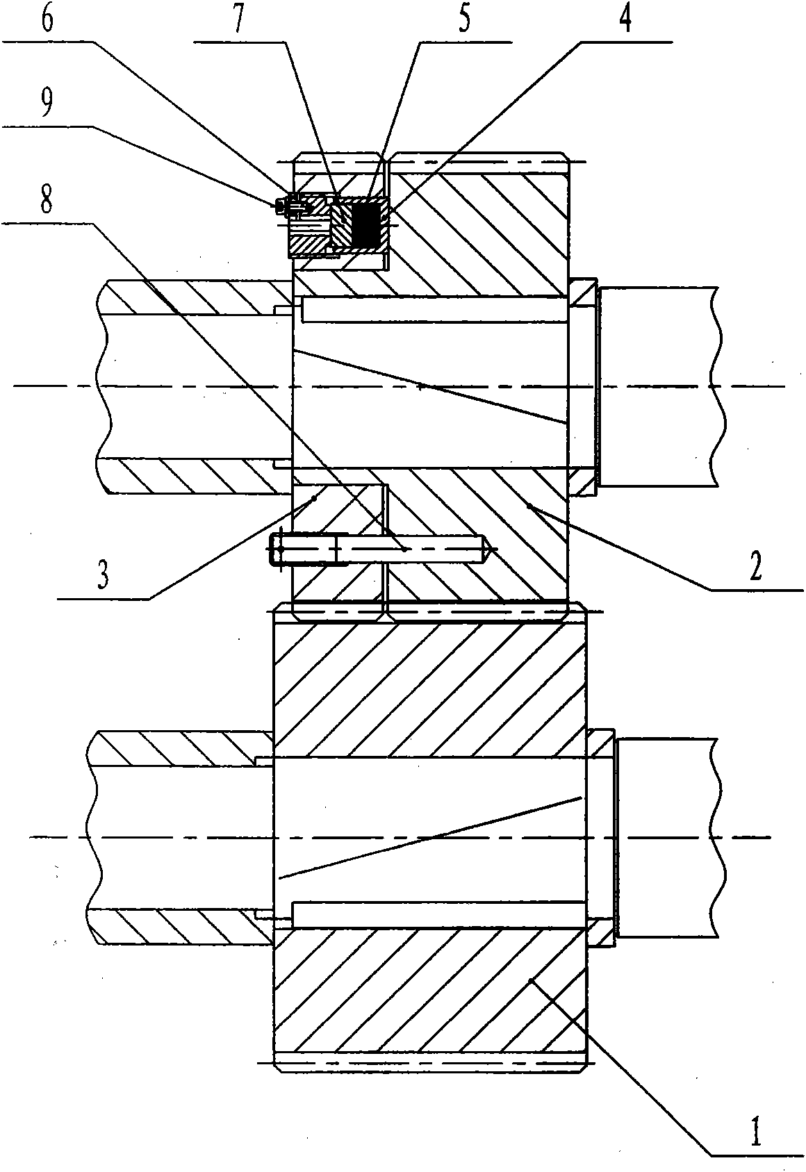
[0015] Such as figure 1 , figure 2 As shown, the present invention is mainly made up of transmission gear 1, fixed gear 2, moving gear 3, guide sleeve 4, spring 5, lock nut 6, pressure ring 7, connector 8 and screw 9 etc. The transmission gear 1 and the fixed gear 2 are helical gears, which mesh with each other, and are connected to the transmission shaft with a key to realize the master and slave transmission; the moving gear 3 is a helical gear, which is fixed on the fixed gear 2 through the connecting piece 8, and the connecting piece 8 is Key or pin, guide sleeve 4 is installed in the end face hole of moving gear 3, spring 5 is installed in the hole of guide sleeve 4, lock nut 6 compresses spring 5 through pressure ring 7, spring 5 is a disc spring, screw 9 prevents locking The tight nut 6 is loose.

[0016] Transmission gear 1, fixed gear 2, and moving gear 3 are carburized and quenched with 20CrMoTi, the carburized layer depth is...


PUM


Abstract

The invention discloses an automatic gear clearance elimination mechanism, used for eliminating a clearance of a transmission gear. The transmission gear is meshed with a fixed gear and is connected to a transmission shaft through a connecting piece, a movable gear is fixed on the fixed gear through a pin or a key, a guide sleeve is installed in an end surface hole of the movable gear, a spring is installed in a hole of the guide sleeve, a locking nut presses a press ring to tightly pressing the spring, and the transmission gear, the fixed gear and the movable gear are all helical gears. By turning the locking nut, the movable gear moves along the connecting piece, a clearance generated by abrasion between the transmission gear and the fixed gear is eliminated, and the clearance of the gear is automatically eliminated. In the invention, the transmission gear and the fixed gear in equipment do not needed to be loosened and re-adjusted for eliminating the gear clearance, the gear clearance can disappear automatically under the action of the pre-tightening force of the spring just by turning the locking nut in the process of initial installation to adjust the pre-tightening force of the spring. The invention has the advantages of convenient installation and use, stable and reliable work and free maintenance.

Description

technical field [0001] The invention relates to a scrapping shear unit used on the cold finish rolling and finishing line of metal strips in the iron and steel and non-ferrous metal industries, especially the scraping shear gear transmission part of medium and thin metal strips (0.2mm-6.0mm) and Other gear transmission occasions. Background technique [0002] As a waste edge treatment equipment after continuous longitudinal shearing of metal strips, scrap shears are widely used in the steel and non-ferrous metal industries. The transmission gear is one of the key mechanisms of the cutting edge shear. Due to the inevitable gap in the ordinary gear transmission structure, there is a slight error in the speed of the transmission system. At the same time, the relative position relationship between the upper and lower shafts will also change, thus affecting the upper and lower correspondence The relative positional relationship of the blades will cause the gap between the blades...

Claims


Application Information

Patent Timeline
IPC IPC(8): F16H55/18F16H55/20B23D33/00
Inventor 李文喜吴春雷吴华涛杨松黄甡李政
Owner XIANGYANG BOYA PRECISION IND EQUIP
Why Eureka
Try Eureka