Vehicular lamp

A technology for vehicles and lamps, which is applied to road vehicles, vehicle parts, vehicle lighting systems, etc., and can solve problems such as the reduction of light in the functional light distribution part, the darkening of the pattern light distribution part 58, and the darkening of the functional light distribution part. Optimal distribution rate, good appearance, and effect of improving appearance

Active Publication Date: 2010-12-08
KOITO MFG CO LTD
View PDF4 Cites 39 Cited by
  • Summary
  • Abstract
  • Description
  • Claims
  • Application Information

AI Technical Summary

Problems solved by technology

[0006] However, if according to Figure 10 And the side blinker 51 of patent document 1, there is the following problem: Most of the light irradiated by the LED light source 54 passes along the length direction of the light guide lens 53, and is emitted from the functional light distribution part 56. Therefore, as Figure 11 As shown, between the functional light distribution part 56 and the light source side light emitting part 57, the pattern light distribution part 58 becomes dark, and the appearance seen from the front of the vehicle deteriorates.
In the case of the side flash of Patent Document 2, the light from the LED light source is distributed substantially uniformly over the entire area of ​​the light guide lens, so that the pattern light distribution part becomes brighter, but the amount of light guided to the functional light distribution part decreases thereby, and the functional light distribution The part is darkened, and there is a problem that the visibility from the side of the vehicle is deteriorated.

Method used


Image

  • Vehicular lamp
  • Vehicular lamp
  • Vehicular lamp

Examples


Embodiment Construction

[0037] Below, with reference to accompanying drawing, the present invention is embodied as the embodiment of side turn signal indicator, in the following embodiment, although various limitations are made to constituent element, kind, combination, shape, relative arrangement etc., these are only It is an example, and the present invention is not limited thereto.

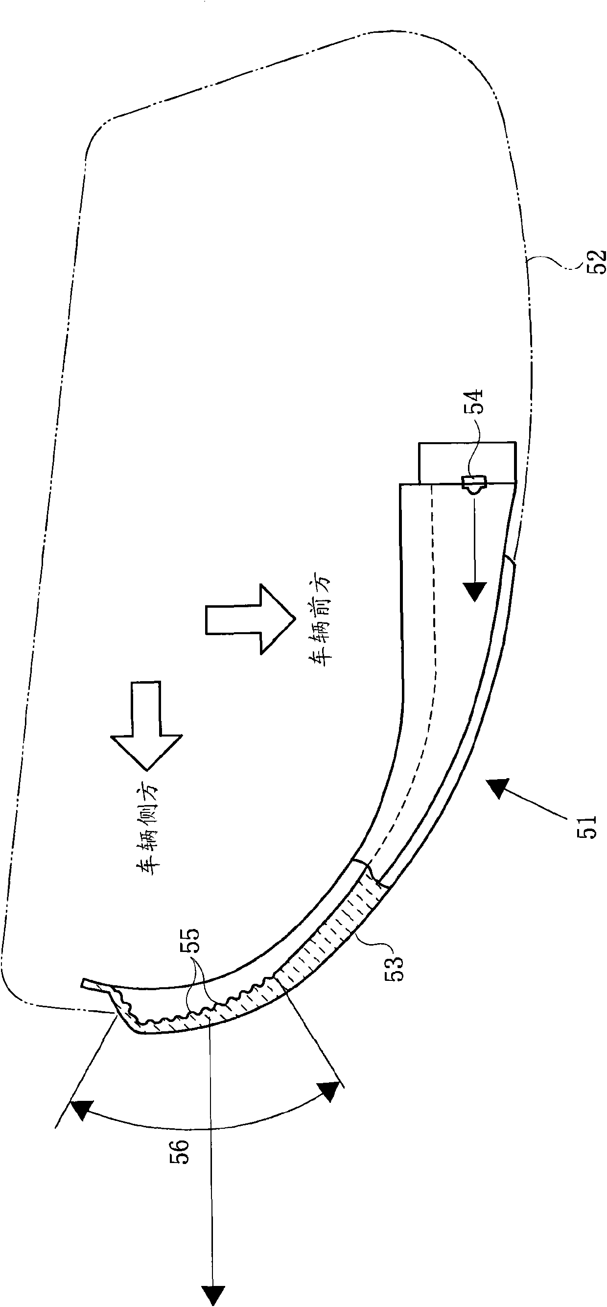
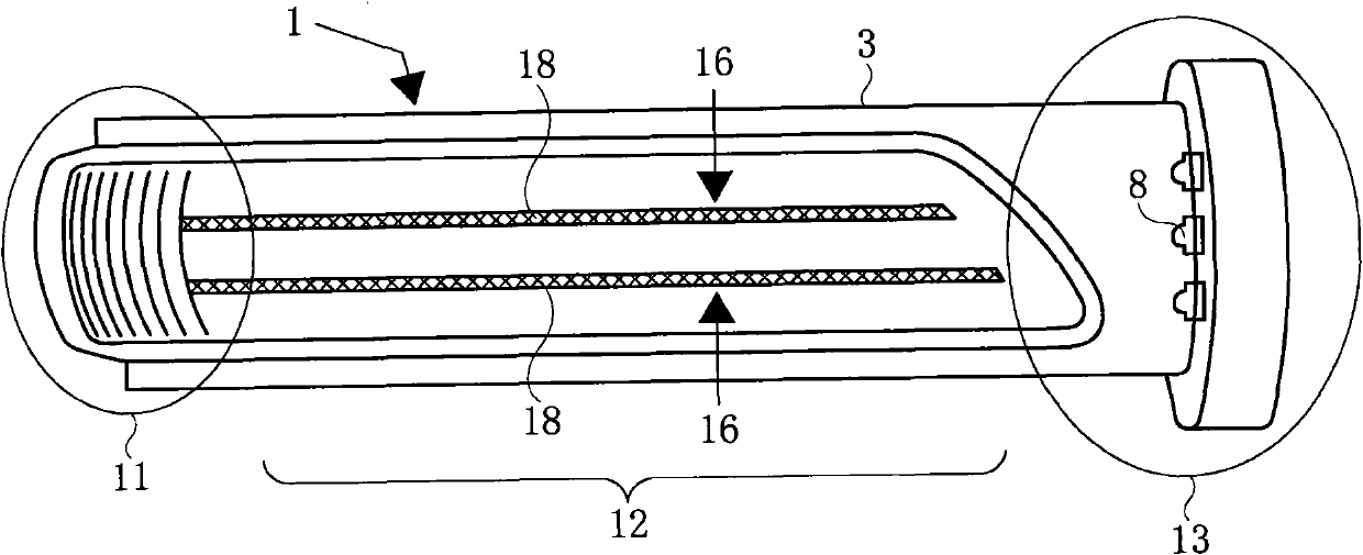
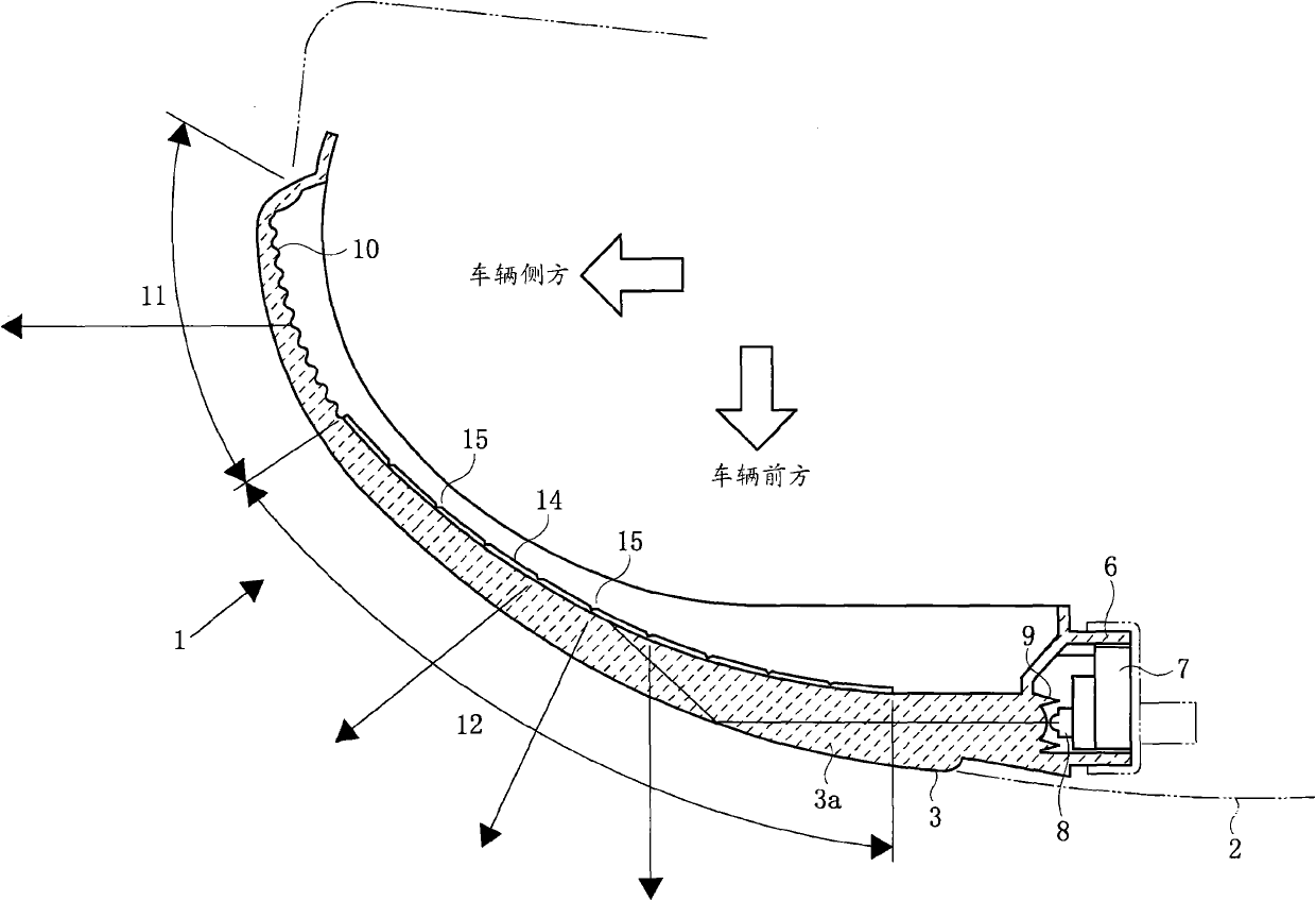
[0038] Such as Figure 1 to Figure 3 As shown, the side blinker 1 of this embodiment is provided with the light guide lens 3 on the front side of the reflector case 2 as in the conventional one. The light guide lens 3 is composed of a strip-shaped lens part 3a and a pair of upper and lower mounting parts 3b, and is formed into a flat arch shape with a transparent synthetic resin material as a whole.

[0039] The mounting portion 3b is held by the inner frame 4 of the mirror housing 2 with a holder 5, and the front surface of the lens portion 3a is exposed from the opening 2a of the mirror housing 2 to the front and s...


PUM


Abstract

It is an object of the present disclosure to provide a vehicular lamp that can distribute light from an LED light source in a balanced manner, illuminate a design light distribution portion with a small amount of light while achieving a good appearance, and brightly illuminate a functional light distribution portion with a sufficient amount of light. In a side turn signal lamp, an LED light source (8) is mounted to a base end of a light guide lens (3). A distal end of the light guide lens (3) curves toward the rear of a vehicle and a functional light distribution portion (11) including light diffusion steps (10) is formed in a curved portion, so that light from the LED light source (8) is diffused toward a side of the vehicle. In a design light distribution portion (12) between the LED light source (8) and the functional light distribution portion (11), a linear optical step (14) is formed on a rear surface of the light guide lens (3) so as to extend in a longitudinal direction of the lens. A portion of light headed from the LED light source (8) toward the functional light distribution portion (11) is reflected by the optical step (14) in front of the vehicle and diffused around the groove portion (15).

Description

technical field [0001] The present invention relates to a lamp for a vehicle in which an LED light source is provided at the base end of a light guide lens bent toward the rear of the vehicle, and a functional light distribution portion is formed at the front end of the light guide lens toward the side of the vehicle. Background technique [0002] As such a vehicle lamp, a side blinker provided on a side reflector of an automobile is conventionally known. For example, Figure 10 The shown side blinker 51 is provided with a light guide lens 53 on the front side of the reflector housing 52 , and an LED light source 54 is provided at the base end of the light guide lens 53 . The front end of the light guide lens 53 is bent toward the rear of the vehicle, and a functional light distribution part 56 composed of a plurality of steps 55 is formed at the curved part. The light from the LED light source 54 is diffused toward the side of the vehicle on the steps 55, forming a light di...

Claims


Application Information

Patent Timeline
Patent Type & Authority Applications(China)
IPC IPC(8): F21S8/10F21V13/00F21V17/00F21V19/00F21W101/02F21Y101/02F21W107/10
CPCB60Q1/2665F21S48/2281F21S48/2237F21S48/2268F21S48/2262B60R1/1207F21S43/237F21S43/243F21S43/245F21S43/249B60Q1/34F21V5/00
Inventor 风冈成彦
Owner KOITO MFG CO LTD
Why Eureka
Try Eureka