Optical touch module

A touch module, optical technology, applied in the direction of instruments, electrical digital data processing, data processing input/output process, etc., can solve the problems affecting the accuracy of light intensity changes of optical sensors, light reflection leakage, optical In order to improve the efficiency of light use, improve accuracy, and prevent light leakage, it can solve problems such as touch failure of the type touch module.

Inactive Publication Date: 2010-12-08
QISDA SUZHOU +1
View PDF2 Cites 10 Cited by
  • Summary
  • Abstract
  • Description
  • Claims
  • Application Information

AI Technical Summary

Problems solved by technology

[0003] However, in actual use, due to the thermal expansion and contraction of the light guide structure under different use environments, the structural deformation will cause an unnecessary gap between the light-emitting unit and the light guide structure. Therefore, this gap will cause the light to emit light The light emitted by the unit is reflected when it is incident on the light incident surface of the light guide structure, so that the light can only partially enter the light guide structure. That is to say, the configuration design adopted above often makes the optical touch module The problem of light reflection and light leakage occurs at the installation position of the light-emitting unit, which affects the accuracy of the optical sensor in judging the change of light intensity. In addition, when the light leakage is serious, it may even cause the optical touch module to fail to touch There is a problem of touch failure at a certain position in the surface

Method used


Image

  • Optical touch module
  • Optical touch module
  • Optical touch module

Examples


Embodiment Construction

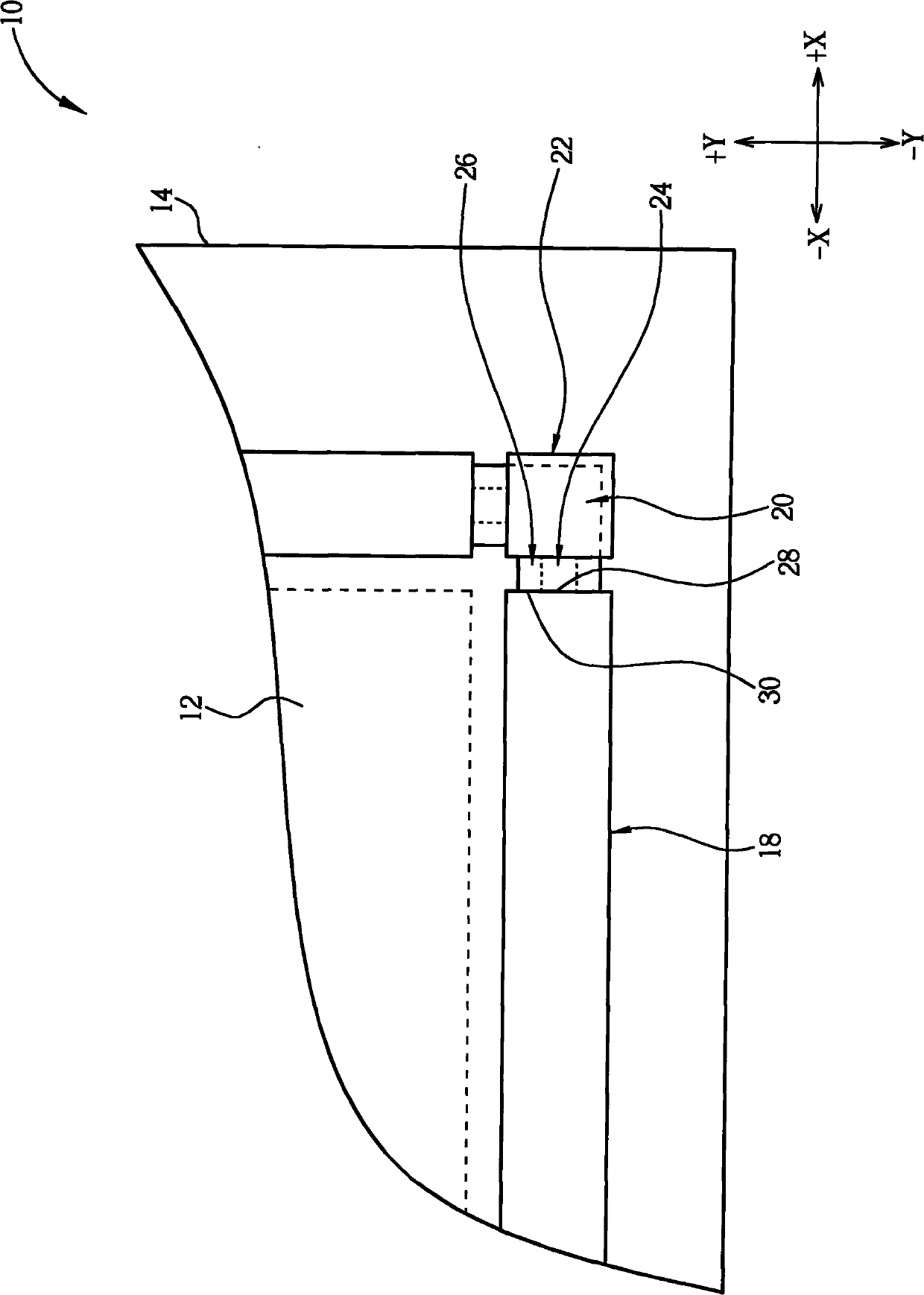
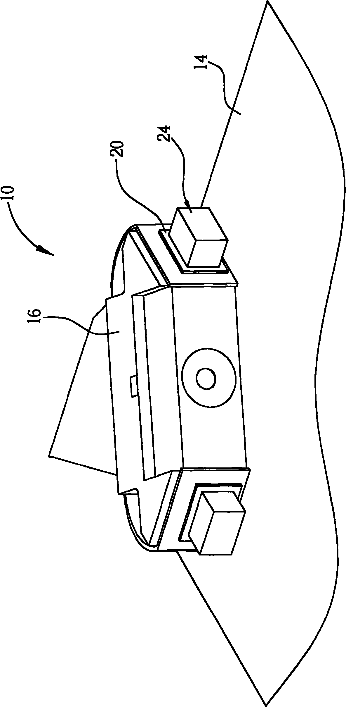
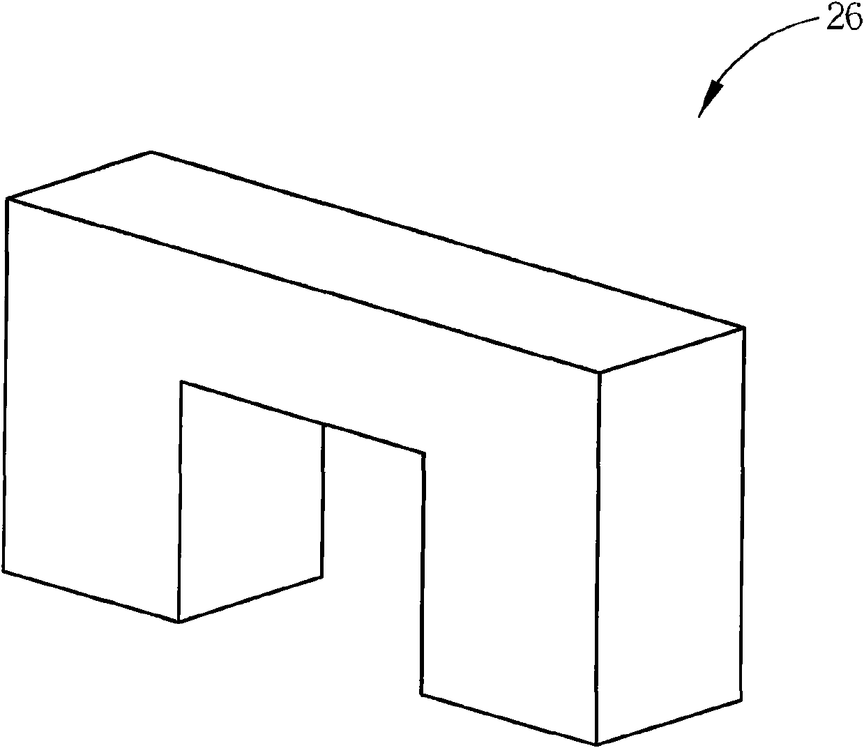
[0027] see figure 1 , which is a schematic diagram of the optical touch module 10 proposed according to the first embodiment of the present invention, represented by figure 1 It can be seen that the optical touch module 10 includes a touch surface 12, a substrate 14, and at least one optical sensor 16 (in figure 1 Show two in), at least one light guide structure 18 (in figure 1 Show four in), at least one elastic member 20 (in figure 1 Show six in), at least one fixed seat 22 (in figure 1 Show two in), at least one light emitting unit 24 (in figure 1 Eight are shown in ), and at least one light-shielding structure 26 (in figure 1 Eight are shown in the figure); the touch surface 12 is located on the substrate 14 for touch operation; the substrate 14 is a plate commonly used in optical touch modules, such as glass or transparent acrylic; The optical sensor 16 captures the image of the touch area toward the touch surface 12, and thereby detects the change of light intensity...


PUM


Abstract

The invention discloses an optical touch module, comprising a touch surface, a substrate, at least one optical sensor, a light guide structure, an elastic element and a light emitting unit. The touch surface is positioned on the substrate, the optical sensor captures the image of a touch zone towards the touch surface; the light guide structure is arranged along one side of the touch surface to guide light into the touch surface. The elastic element is arranged at one end part of the light guide structure. The light emitting unit is arranged between the light guide structure and the elastic element, and is butted against the elastic element to allow the light exit surface of the light emitting unit to be closely adjacent to the light incoming surface of the light guide structure substantially. Therefore, the optical touch module provided by the invention can solve the problem that gaps appear between the light emitting unit and the light guide structure due to that the light guide structure has structural distortion caused by expansion on heating and contraction on cooling under different use environments, provides good assembling effect and effectively eliminate light leakage problem.

Description

technical field [0001] The present invention relates to an optical touch module, in particular to a device that utilizes the elastic force provided by the elastic member to make the light-emitting unit close to the light guide structure and uses a light-shielding structure to block the light reflected from the light guide structure. Optical touch module. Background technique [0002] Generally speaking, the optical touch module uses the light receiving and blocking principle to detect the relative position of the finger or stylus on the touch surface. Its components include a substrate, a light-emitting unit, an optical sensor, and a guide. The common configuration of the light structure is that the light guide structure is arranged along the side of the touch surface on the substrate, the light emitting unit is arranged on the substrate corresponding to the light incident surface of the light guide structure, and the optical sensor It is arranged at the position correspond...

Claims


Application Information

Patent Timeline
Patent Type & Authority Applications(China)
IPC IPC(8): G06F3/042
Inventor 陈建维陈志宏
Owner QISDA SUZHOU
Why Eureka
Try Eureka