Direct current quick breaker

A technology of rapid circuit breaking and circuit breaker body, which is applied to circuit breaker components, circuits, electrical components, etc., can solve the problems of elongated arc, increased arc burning time, and large arc resistance, and achieves improved arc resistance and arc voltage. The effect of reducing the arcing time and improving the arc extinguishing ability

Active Publication Date: 2010-12-08
中国船舶重工集团公司第七一二研究所
View PDF6 Cites 11 Cited by
  • Summary
  • Abstract
  • Description
  • Claims
  • Application Information

AI Technical Summary

Problems solved by technology

[0002] Most of the existing DC fast circuit breakers use traditional grid-type arc extinguishing chambers. The metal grids have a regular symmetrical inverted V-shaped structure, and the notches of the metal grids are flush with each other, which allows the arc to enter the extinguishing chamber. The resistance encountered by the arc chamber is relatively large, especially when the large current is broken, the arc cannot quickly enter the metal grid, the arc voltage rises slowly, and the arcing time increases. In addition, the metal grid with the flat end face of the slot It is also not conducive to elongating the arc and is not conducive to the extinguishing of the arc

Method used


Image

  • Direct current quick breaker
  • Direct current quick breaker
  • Direct current quick breaker

Examples


Embodiment 1

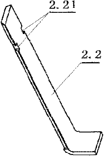
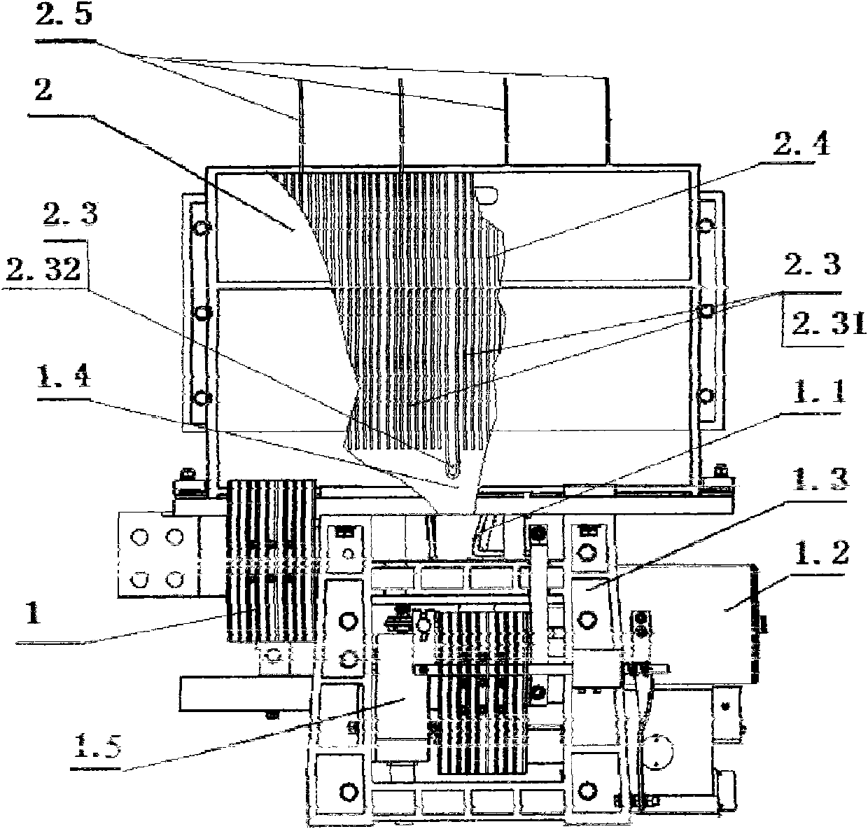
[0035] like figure 1 , 2 As shown in , 8: it is a DC fast circuit breaker, which has a circuit breaker body 1 and an arc extinguishing chamber 2; the circuit breaker body 1 has a contact system 11, an operating mechanism 1.2, a frame 1.3, and a release device 1.5; The arc extinguishing chamber 2 has a pair of insulating shells 2.1, an arc strike angle 2.2, and the inner cavity of the arc extinguishing chamber 2 has a metal grid 2.3, an insulating grid 2.4, and a diaphragm 2.5; wherein the metal grid 2.3 and the insulating grid 2.4 Located in the middle of the arc extinguishing chamber 2, the transverse partition 2.5 is located on the upper part of the arc extinguishing chamber 2; this embodiment is for example figure 2 As shown: there are a pair of insulating shells 2.1, a pair of arc strike angles 2.2, a group of metal grids 2.3, insulating grids 2.4, and four transverse partitions 2.5 to form an arc extinguishing chamber 2; the metal grids 2.3 are flat The part is the fro...

Embodiment 2

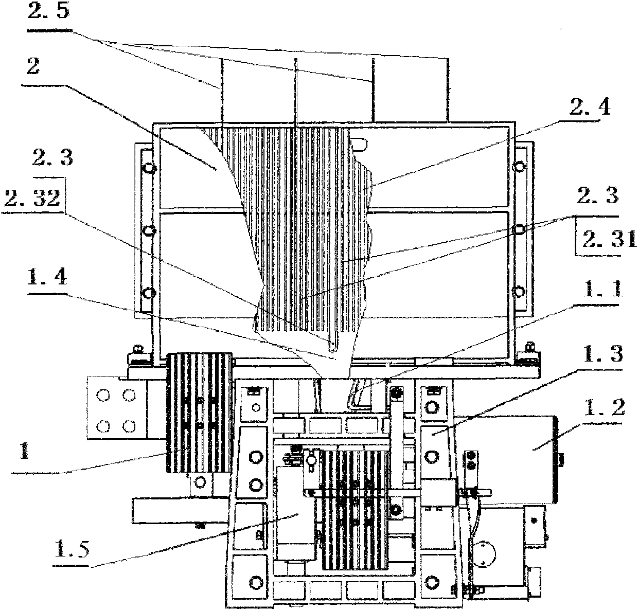
[0037] Different from the above-mentioned embodiment 1, the arc extinguishing chamber 2 of this embodiment is as Figure 9 As shown: there are a pair of insulating shells 2.1, a pair of arc striking angles 2.2, a group of metal grids 2.3, insulating grids 2.4, and two transverse partitions 2.5 to form the arc extinguishing chamber 2; the structure of this embodiment reduces the straight plate type The number of metal grids 2.31, insulating grids 2.4, and transverse partitions 2.5, and the length of the insulating housing 2.1 are correspondingly reduced. This embodiment can be applied to circuit breakers with lower voltage levels. The angle of the notch 2.01 of the straight metal grid sheet 2.31 is 90 degrees. The notch 2.02 angle of the U-shaped metal grid 232 is 105 degrees, and the distance between the metal grids 23 is 8 mm.

Embodiment 3

[0039] Different from the above-mentioned embodiment 2, the angle of the notch 2.01 of the straight metal grid 2.31 in this embodiment is 40 degrees; the angle of the notch 2.02 of the U-shaped metal grid 2.32 is 75 degrees, and the The metal grid pieces 2.3 maintain a spacing distance of 2 mm.


PUM


Abstract

The invention relates to a direct current quick breaker, in particular to a direct current quick breaker with high requirement for short circuit breaking current. The breaker comprises a breaker body and an arc extinguish chamber, wherein the arc extinguish chamber comprises a pair of insulated shells and an arcing ring; the cavity of the arc extinguish chamber comprises a metal grid, an insulated grid and a transverse clapboard; the metal grid and the insulated grid are positioned in the middle of the arc extinguish chamber; the transverse clapboard is positioned on the upper part of the arc extinguish chamber; one side, which faces the bottom of the arc extinguish chamber, of the metal grid is a lower side provided with a notch having a downward opening; and two types of metal grids, namely a straight-panel metal grid and a U-shaped metal grid are provided. The breaker has the advantages of quickly establishing arc voltage, reducing the resistance of electric arc entering the arc extinguish chamber, lengthening electric arc, shortening arcing time, enhancing arc extinguishing capability of the arc extinguish chamber, along with simple structure, small overall dimension, convenient assembly and maintenance and the like.

Description

technical field [0001] The invention relates to a direct current fast circuit breaker, which is particularly suitable as a direct current fast circuit breaker with high requirements for short-circuit breaking current. Background technique [0002] Most of the existing DC fast circuit breakers use traditional grid-type arc extinguishing chambers. The metal grids have a regular symmetrical inverted V-shaped structure, and the notches of the metal grids are flush with each other, which allows the arc to enter the extinguishing chamber. The resistance encountered by the arc chamber is relatively large, especially when the large current is broken, the arc cannot quickly enter the metal grid, the arc voltage rises slowly, and the arcing time increases. In addition, the metal grid with the flat end face of the slot It is also not conducive to elongating the arc and is not conducive to the extinguishing of the arc. SUMMARY OF THE INVENTION [0003] The object of the present inven...

Claims


Application Information

Patent Timeline
Patent Type & Authority Applications(China)
IPC IPC(8): H01H73/18H01H9/36
Inventor 赵成宏马子文曹鹏飞涂煜包涌泉章程
Owner 中国船舶重工集团公司第七一二研究所
Why Eureka
Try Eureka