Optical line terminal equipment, protection method and passive optical network system

A passive optical network and optical line terminal technology, which is applied in the selection device of multiplexing system, transmission system, electromagnetic wave transmission system, etc., can solve the problem of long protection switching time, longer protection switching time, and ONU re-ranging and other problems, to achieve the effect of improving rapid recovery capability, saving network construction costs, and reducing switching time.

Inactive Publication Date: 2010-12-08
HUAWEI TECH CO LTD
View PDF4 Cites 24 Cited by
  • Summary
  • Abstract
  • Description
  • Claims
  • Application Information

AI Technical Summary

Problems solved by technology

However, due to the different transmission delays on the active and standby paths, all ONUs need to re-range when switching from the main path to the standby path. The more ONUs, the longer the protection switching time
Moreover, the PON line terminal (OLT) is directly connected to the optical fiber, so that when the main optical fiber is intact but the OLT fails, the backup OLT must also be used while the standby optical fiber is enabled. Different standby paths make the protection switching time longer

Method used


Image

  • Optical line terminal equipment, protection method and passive optical network system
  • Optical line terminal equipment, protection method and passive optical network system
  • Optical line terminal equipment, protection method and passive optical network system

Examples


Embodiment Construction

[0020] The following will clearly and completely describe the technical solutions in the embodiments of the present invention with reference to the accompanying drawings in the embodiments of the present invention. Obviously, the described embodiments are some of the embodiments of the present invention, but not all of them. Based on the embodiments of the present invention, all other embodiments obtained by persons of ordinary skill in the art without creative efforts fall within the protection scope of the present invention.

[0021] It should be noted that the word "connected" used in the embodiments of the present invention may indicate a direct connection or an indirect connection, that is, there are other intervening elements.

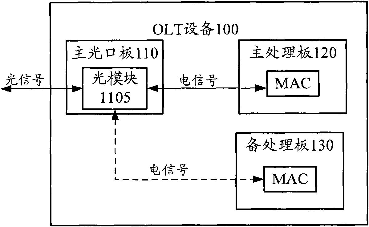
[0022] figure 2 is a schematic block diagram showing a PON optical line terminal (OLT) device 100 according to an embodiment of the present invention. The OLT device 100 includes a main optical port board 110 , a main processing board 120 and a...


PUM


Abstract

The embodiment of the invention provides optical line terminal equipment, a protection method and a passive optical network system. The equipment comprises a main processing board, a standby processing board and a main optical interface, wherein the main processing board comprises a main processing module used for carrying out PON protocol layer processing and service processing; the standby processing board comprises a standby processing module used for carrying out PON protocol layer processing and service processing; and the main optical interface comprises an optical module used for converting optical signals into electrical signals or converting electrical signals into optical signals. The electrical signals are transmitted between the main / standby processing boards and the main optical interface, and the optical signals are transmitted between the main optical interface and an optical network unit. The standby processing board backs up the equalization delay of the main processing board corresponding to the optical network unit in the PON system, and when the main / standby processing boards are switched, the equalization delay of the main processing board is used as the equalization delay of the standby processing board. The optical line terminal equipment and the protection method of the passive optical network according to the embodiment of the invention can fully utilize the current optical distribution network and reduce the protection switching time.

Description

technical field [0001] Embodiments of the present invention relate to a passive optical network (Passive Optical Network; PON), and in particular to an optical line terminal (Optical Line Terminal; OLT) device and protection method in the PON and a PON system. Background technique [0002] With the rise of services such as video-on-demand, high-definition TV, and online games, users' demand for network bandwidth is increasing. Passive optical network (PON) technology can effectively guarantee the access bandwidth of the "last mile", and has become an optical It is one of the mainstream technologies of the access network. figure 1 A schematic block diagram of a typical PON system architecture is shown. Such as figure 1 As shown, the PON includes an optical line terminal (OLT), an optical network unit (Optical Network Unit; ONU) and an optical distribution network (Optical Distribution Network; ODN). The OLT is located at the central office, and the ONU is located at the us...

Claims


Application Information

Patent Timeline
Patent Type & Authority Applications(China)
IPC IPC(8): H04Q11/00H04B10/12H04B10/032
Inventor 蒋红丽陈娟余丽苹
Owner HUAWEI TECH CO LTD
Why Eureka
Try Eureka