
Indoor base station system

An indoor base station and antenna feeder system technology, which is applied in network planning, electrical components, radio/inductive link selection and arrangement, etc., can solve problems such as unresolved capacity problems, and achieve the effect of reducing network construction costs

Active Publication Date: 2006-08-16
HUAWEI TECH CO LTD
View PDF0 Cites 12 Cited by
  • Summary
  • Abstract
  • Description
  • Claims
  • Application Information

AI Technical Summary

Problems solved by technology

That is, the solution only solves the coverage problem, but does not solve the capacity problem

Method used


Image

  • Indoor base station system
  • Indoor base station system

Examples


Embodiment Construction

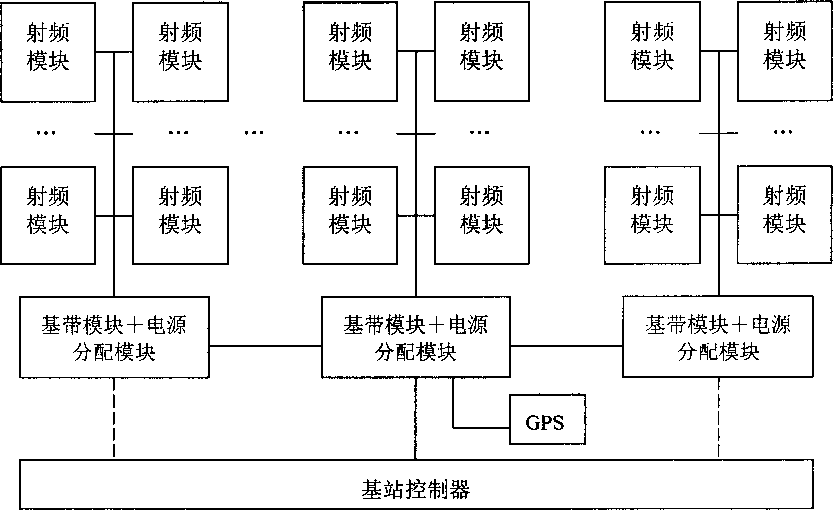
[0029] The core of the present invention is to realize the indoor base station system by using the distributed setting of the baseband processing part and the radio frequency processing part to solve the problems of indoor coverage and capacity of the mobile public network, and at the same time solve the problems of cost and full frequency band support.

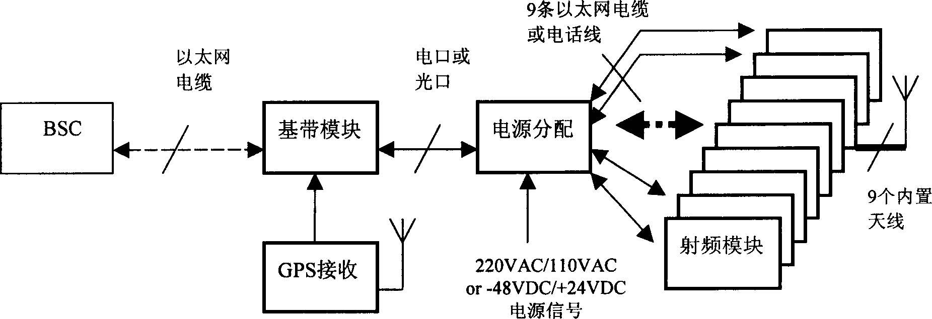
[0030] What the indoor base station system of the present invention adopts is a distributed PICO (pico) base station system, and the specific structure is as follows figure 1 shown, including:

[0031] Baseband module: connected to the base station controller, used to process the baseband uplink and downlink signals, that is, to realize the sending and receiving processing of baseband signals, and the baseband module is connected to the remote radio frequency module;

[0032] Radio frequency module: The independently set radio frequency module performs data interaction with the baseband module through the telephone line or Et...


PUM


Abstract

An indoor base station system that is a distribution base-station system mainly includes: the base-band module and the radio-frequency module, the self-setting base-band module and radio-frequency module are long connection, the base-band module use for dispatcher processing of the base-band signal and connect with the base-band controller, the radio-frequency module use for dispatcher processing of the radio-frequency signal. The invention may realize the omnidirectional covering indoor, do not change any part of the building. Therefore, the realization of the invention, has effectively solved the capacity and in-depth covering question of the indoor covering, also greatly reduces the net cost of indoor covering.

Description

technical field [0001] The present invention relates to the technical field of wireless communication, in particular to an indoor base station system. Background technique [0002] In wireless mobile networks, indoor coverage has always been a difficult coverage area for network operators. For CDMA (Code Division Multiple Access) systems, with the continuous development of data services, the demand for good indoor coverage is becoming more and more urgent. How to effectively resolve the contradiction between indoor coverage and capacity, while meeting the needs of voice and data services, is a practical problem that must be solved for wireless communication network coverage. [0003] In addition, most buildings did not consider the indoor coverage of future mobile networks at the initial stage of construction, and did not reserve various interfaces and network infrastructure designs for wireless coverage in advance. This existing objective condition makes the layout and co...

Claims


Application Information

Patent Timeline
Patent Type & Authority Applications(China)
IPC IPC(8): H04Q7/30H04W16/20H04W88/08
Inventor 赵天忠张志东朱国霞
Owner HUAWEI TECH CO LTD
Learn More