System for controlling hybrid energy system

A technology of mixing energy and energy, applied in control devices, auxiliary energy regeneration, hybrid vehicles, etc., can solve the problems of not considering non-traction load, not easy to obtain, etc.

Inactive Publication Date: 2013-11-27
CATERPILLAR INC
View PDF1 Cites 2 Cited by
  • Summary
  • Abstract
  • Description
  • Claims
  • Application Information

AI Technical Summary

Problems solved by technology

While chart data is readily available for on-road applications such as permanent highways, it is less readily available for non-road applications such as temporary construction sites
Furthermore, the method of the '396 patent charges and discharges the battery according to changing traction loads, energy demand and regeneration, but it does not take into account changing non-traction loads

Method used


Image

  • System for controlling hybrid energy system
  • System for controlling hybrid energy system

Examples


Embodiment Construction

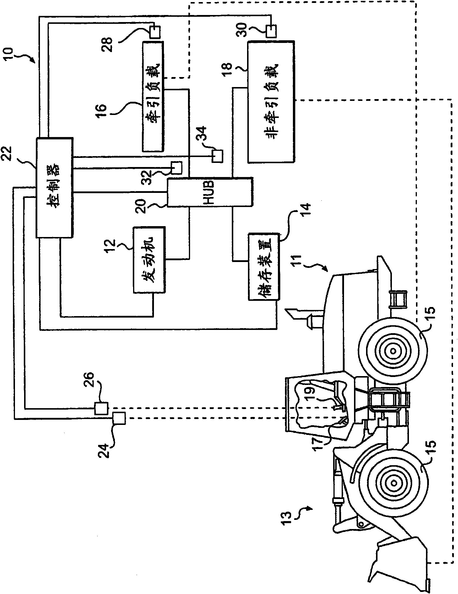
[0010] figure 1 An exemplary hybrid energy system 10 is shown. Specifically, the system 10 may include an engine 12 and a storage device 14 and may be configured to selectively energize traction loads 16 and non-traction loads 18 via a hub 20 . Collector 20 may selectively receive energy from engine 12 , storage device 14 , traction load 16 and / or non-traction load 18 and direct the received energy to engine 12 , storage device 14 , traction load 16 and / or or non-tracting load 18. System 10 may also include a controller 22 operable to control operation of engine 12 and storage device 14 and / or to introduce energy to one or more components of system 10 via collector 20 . System 10 may be operatively connected to machine 11 for propelling machine 11 relative to a ground surface and / or manipulating implement 13 operably connected to machine 11 . The machine 11 may be a stationary or mobile machine performing some type of work related to an industry such as mining, construction...


PUM


Abstract

A method includes identifying a first operating sequence of a repeated operation of at least one non-traction load. The method also includes determining first and second parameters respectively indicative of a requested energy and output energy of the at least one non-traction load and comparing the determined first and second parameters at a plurality of time increments of the first operating sequence. The method also includes determining a third parameter of the hybrid energy system indicative of energy regenerated from the at least one non-traction load and monitoring the third parameter at the plurality of time increments of the first operating sequence. The method also includes determining at least one of an energy deficiency or an energy surplus associated with the non-traction load of the hybrid energy system and selectively adjusting energy stored within the storage device during at least a portion of a second operating sequence.

Description

technical field [0001] The present invention relates to hybrid energy systems, and more particularly to methods and apparatus for controlling hybrid energy systems. Background technique [0002] A hybrid energy system typically includes an engine whose prime mover, such as a crankshaft, is mechanically decoupled / uncoupled from one or more loads, such as traction loads and / or non-traction loads. Hybrid energy systems typically also include an energy storage device configured to store energy received from the engine in an engine overpower mode or energy received from a load in an energy regeneration mode. The engine and storage device are electrically coupled to the load through an electric motor to enable the engine to also operate as an energy source instead of a conventional drive mechanism and to allow the storage device to recover regenerative energy. The amount and frequency of energy required to operate and regenerated in terms of load is generally independent of the a...

Claims


Application Information

Patent Timeline
Patent Type & Authority Patents(China)
IPC IPC(8): B60W20/00B60L50/16
CPCY02T10/6286B60W2540/12B60W2540/10B60W10/06B60W2710/0677B60W2510/244B60L2240/64B60L1/003B60L2240/486B60W20/00Y02T10/7291Y02T90/16B60W2710/105B60L2200/40B60L1/20B60K6/12B60W2710/086B60L11/14Y02T10/7077B60W10/26Y02T10/6208B60W10/08B60L50/16Y02T10/62Y02T10/7072Y02T10/72Y02P90/60B60W10/24B60W20/10B60W2710/24Y02T10/70
Inventor B·D·霍夫S·阿卡萨姆
Owner CATERPILLAR INC
Why Eureka
Try Eureka