
Fuel reformer and fuel supply system using the same

A technology of fuel supply system and reforming device, which is applied in the direction of charging system, liquid fuel feeder, combustion air/combustion-air treatment, etc. The problem of uneven performance, etc., achieves the effect of suppressing adverse effects, suppressing adverse effects on the environment, and suppressing the decline in combustion efficiency

Inactive Publication Date: 2013-01-16
速水 哲哉
View PDF4 Cites 0 Cited by
  • Summary
  • Abstract
  • Description
  • Claims
  • Application Information

AI Technical Summary

Problems solved by technology

However, as disclosed in Patent Document 1 and Patent Document 4, when ultrasonic vibration is applied to the liquid fuel in the fuel tank to reform the liquid fuel, the reformed fuel undergoes a mixing process with air to reach Combustion stroke, but since there is a distance from the tank to the combustion stroke, there is a possibility of reforming and deteriorating, and it is impossible to reform the entire fuel contained in the tank equally, so the disadvantage of uneven combustion performance occurs
[0011] Moreover, in the fuel improvement device described in Patent Document 2, since the ultrasonic vibration device is arranged on a normal pipe, the efficiency of atomization of the passing liquid fuel is poor. In the fuel oil reforming device, the liquid fuel that is vibrated by the ultrasonic vibrator is only the fuel that passes through the fuel oil filter bracket before being sent to the fuel oil outflow pipe. Since the passing speed of the fuel is fast, there is a problem that it cannot be fully processed. Defects of modification (micronization)
[0012] In addition, since fuel is supplied at a large flow rate to a large-displacement internal combustion engine such as a ship or a diesel engine, there is a disadvantage that a sufficient effect cannot be obtained by the conventional method.
In addition, in the case of a fuel-injected internal combustion engine having a common rail, there is a problem of insufficient pressure when installed immediately after the fuel pump.

Method used


Image

  • Fuel reformer and fuel supply system using the same
  • Fuel reformer and fuel supply system using the same
  • Fuel reformer and fuel supply system using the same

Examples


Embodiment 1

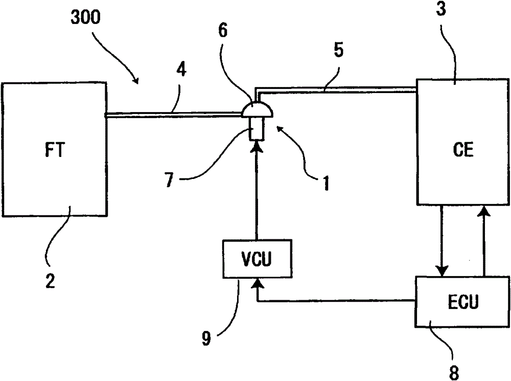
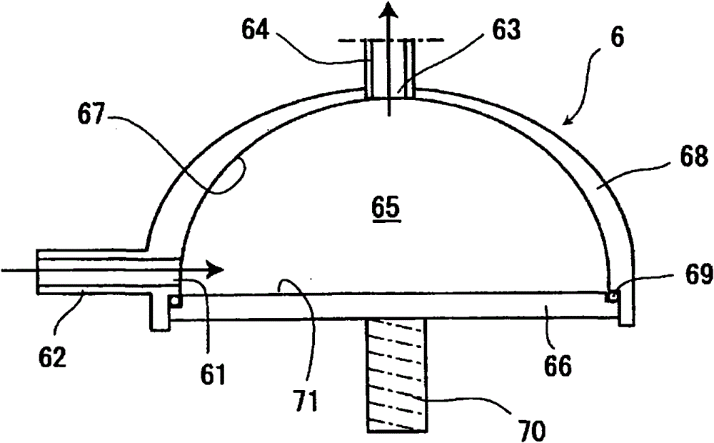
[0095] Such as figure 1 As shown, the fuel reforming device 1 of the present invention is arranged on the pipes 4 and 5 connecting the fuel tank 2 and the internal combustion engine 3 to form a first fuel supply system 300, and is a reforming part in which liquid fuel flows 6, and an ultrasonic transducer (specifically, a bolted Langevin transducer (BLT)) 7 for applying ultrasonic vibration to the reforming portion 6 . Furthermore, the BLT 7 is controlled by a vibrator control unit (VCU) 9 that outputs a signal corresponding to the signal based on a signal from an engine control unit (ECU) 8 that controls the internal combustion engine 3 . As the above-mentioned internal combustion engine 3, it may be a gasoline engine or a diesel engine that mixes liquid fuel with air through a carburetor and sends it to a combustion chamber, or may be a gasoline engine or a diesel engine equipped with a fuel injection pump that directly injects liquid fuel into a combustion chamber. Diesel ...

Embodiment 2

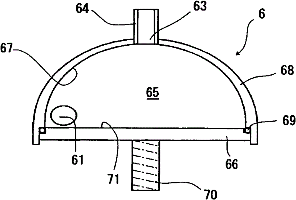
[0102] In the reforming part 6 of the first embodiment, the outflow direction of the liquid fuel is the same as the direction in which the ultrasonic vibration is applied. Figure 4 The reforming unit 6A of the fuel reforming device 1 of the illustrated embodiment 2 is such that the outflow direction of the liquid fuel from the reforming space 65 is the direction along the swirl of the liquid fuel from the top of the reforming space 65, in other words, It is perpendicular to the application direction of the above-mentioned ultrasonic vibration. Also in the modified portion 6A shown in the second embodiment, the same effect as that in the first embodiment can be obtained. In addition, in Figure 4 In Example 2 shown, the same parts as in Example 1 or parts having the same effect are attached with the same symbols and their descriptions are omitted.

Embodiment 3

[0104] Figure 5 The reforming part 6B of the fuel reforming device 1 shown in Embodiment 3 is characterized in that the positions of the inlet 63 and the outlet 64 of the reforming part 6 in Embodiment 1 are substantially reversed, and the reforming space 65 The vibrating plate 66 necessarily has an inverted dome shape, and the vibrating plate 66 applies ultrasonic vibrations to the liquid fuel in the reforming space 65 from above the reforming space 65 . At this time, the liquid fuel flowing into the reforming space 65 from the inflow port 61 ′ moves toward the vibrating surface in a spiral shape while being exposed to ultrasonic vibrations toward the vibrating surface 71 , and moves from the outflow port 63 ′ to the vibrating surface 71 along the vibrating surface 71 ′. The internal combustion engine 3 moves. In this case as well, the same effect as in the case of the first or second embodiment described above can be obtained.

[0105] For each of the above embodiments 1,...


PUM


Abstract

A fuel reformer for fully reforming (fine-graining) liquid fuel fed to an internal combustion engine including an internal combustion engine with large displacement and a fuel supply system using the same. A fuel reformer comprising an inflow port which is provided in a pipe connecting a fuel tank and an internal combustion engine and into which fuel flows, an outflow port out of which the fuel flows, a reforming space located between the inflow port and the outflow port, a vibrating portion provided on at least one side of the reforming space, and an ultrasonic vibrator for vibrating the vibrating portion, and generating nanobubbles by applying an ultrasonic wave to the fuel which is passing, comprises a fuel rotating mechanism for rotating the liquid fuel which flows in from the inflow port along the vibrating surface of the vibrating portion by the vibration of the vibrating portion and a perpendicular moving mechanism for spirally moving the liquid fuel perpendicularly to the vibrating surface toward the outflow port.

Description

technical field [0001] The present invention relates to a fuel reforming device and a fuel supply system using the fuel reforming device. To upgrade. Background technique [0002] Patent Document 1 provides a device for the purpose of pre-gasifying fuel supplied to an internal combustion engine for complete combustion. Ultrasonic vibrations are generated in a tank containing fuel for an internal combustion engine to decompose the fuel into ultrafine particles, and then the fuel is supplied to the internal combustion engine. Vaporize it before feeding it to the internal combustion engine. Specifically, the gasification generating device is composed of a gasification box, an output vibrating element built in the gasification box, and an empty burning prevention switch. [0003] Patent Document 2 provides a fuel improvement device in which an ultrasonic vibrator is installed on a fuel path to atomize fuel, and a magnet or electromagnet is installed downstream thereof to furth...

Claims


Application Information

Patent Timeline
Patent Type & Authority Patents(China)
IPC IPC(8): F02M27/08
CPCY02T10/126Y02T10/12B82Y30/00F02B51/06F02M27/08F02M37/0017
Inventor 速水哲哉元木久一
Owner 速水 哲哉
Learn More