
Wireless receiver with receive diversity

A technology for receivers and receiving signals, applied in diversity/multi-antenna systems, space transmit diversity, radio transmission systems, etc., can solve the problem of increased calculation costs of receivers

Active Publication Date: 2010-12-08
NVIDIA TECH UK
View PDF3 Cites 9 Cited by
  • Summary
  • Abstract
  • Description
  • Claims
  • Application Information

AI Technical Summary

Problems solved by technology

[0009] Although space diversity provides an improvement in the error performance of the receiver, the increased "dimensionality" of the receiver also causes an increase in computational cost

Method used


Image

  • Wireless receiver with receive diversity
  • Wireless receiver with receive diversity
  • Wireless receiver with receive diversity

Examples


Embodiment Construction

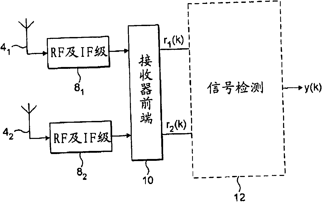
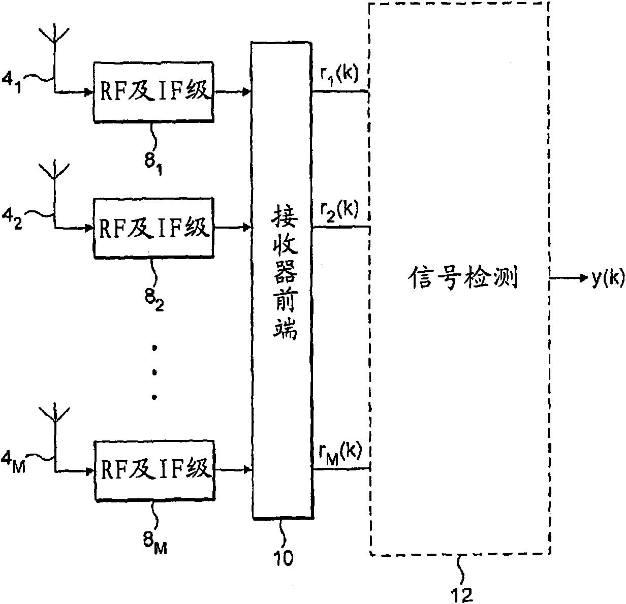
[0052] figure 2 is a schematic block diagram of an example wireless receiver for implementing a two-dimensional receive diversity scheme. The receiver consists of two spatially separated antennas 4 1 and 4 2 . The antennas are typically 1 / 4 to 1 wavelength apart. For example, at 2 GHz the wavelength is about 5 cm, so isolation in this range is achievable in mobile phones and the like. Below about 1 / 4 wavelength, the diversity effect tends to become negligible as the channels become more correlated and experience similar disturbances (noise and / or interference).

[0053] The receiver also includes a first radio frequency (RF) and intermediate frequency (IF) stage block 8 1 , the second RF and IF stage block 8 2 , and the receiver front end 10. First Antenna 4 1 Coupled to the first RF / IF stage block 8 1 input, while the second antenna 4 2 Coupled to the second RF / IF stage block 8 2 input of. 8 per RF / IF stage block 1 and 8 2 The output of is coupled to the input ...


PUM


Abstract

A wireless receiver and corresponding method for receiving a signal transmitted by a transmitter. The receiver comprises: a plurality of antennas each for receiving a version of the signal via a different propagation channel and providing that version at a respective input, and signal processing means configured to operate diversity processing of a supplied number of the inputs for use in performing detection of the signal. The receiver further comprises: channel parameter estimation means configured to estimate one or more channel parameters on the propagation channels; and selection means configured to select only a subset of the inputs to implement a specific dimensionality of the receiver diversity processing, in dependence on the one or more channel parameters indicative of channel conditions on the propagation channels.

Description

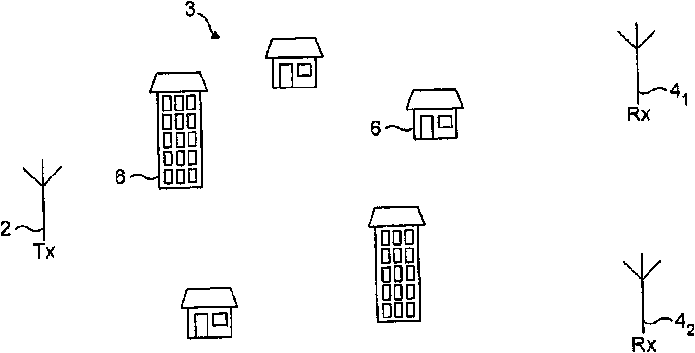
technical field [0001] The present invention relates to receive diversity in wireless receivers. Background technique [0002] In wireless communication systems, communication is accomplished by a transmitter emitting radio frequency (RF) signals to be collected by a receiver. [0003] Multipath fading occurs when a signal travels from a transmitter to a receiver through multiple propagation paths, resulting in multiple copies of the same signal being received that interfere with each other. figure 1 is a (highly schematic) illustration of the effects of multipath fading. Here, the transmit antenna 2 broadcasts the signal over an area 3 that includes a number of buildings 6 or other obstacles that block and / or reflect the signal. The result is that at any given point, the received signal will be the superposition of multiple copies of the signal received via multiple propagation paths. Over a range of locations, the received signal strength thus displays a pattern of peak...

Claims


Application Information

Patent Timeline
Patent Type & Authority Applications(China)
IPC IPC(8): H04B7/08H04B7/02
CPCH04B7/0874H04B7/02H04B7/04
Inventor C·卢施S·赫克特S·阿尔普雷斯P·琼斯
Owner NVIDIA TECH UK
Learn More