Arc-shaped cutting anastomat

A stapler and arc-shaped technology, applied in the field of arc-shaped cutting staplers, can solve the problems of inconvenient firing, difficult assembly, large contact area, etc., and achieves avoiding the phenomenon of bevel, good assembly firmness, and high operation safety. Effect

Active Publication Date: 2010-12-15
CHANGZHOU JIANRUIBAO MEDICAL DEVICES
View PDF3 Cites 720 Cited by
  • Summary
  • Abstract
  • Description
  • Claims
  • Application Information

AI Technical Summary

Problems solved by technology

There are certain disadvantages in the existing arc-shaped cutting stapler: first, the cutting knife is fixed on the knife seat, and the knife seat is fixedly connected with the pusher piece. The three of them need to move forward synchronously, because there is a gap between the assembled nail pusher and the knife seat, which will cause the movement of the nail pusher, cutting knife and knife seat to be out of sync or cause the cutting knife to not completely cut off the tissue. Phenomenon; and because the workpieces of the nail pusher, cutting knife and knife seat are small, the assembly is difficult. If the nail pusher, cutting knife and knife seat are not assembled firmly, the cutting knife may shake when cutting tissue , and lead to phenomena such as oblique cutting or incomplete cutting of tissue; on the other hand, during the operation of the doctor, the resistance generated by the pusher piece when pushing t

Method used


Image

  • Arc-shaped cutting anastomat
  • Arc-shaped cutting anastomat
  • Arc-shaped cutting anastomat

Examples


Embodiment Construction

[0032] The present invention will be described in further detail below in conjunction with the embodiments given in the accompanying drawings.

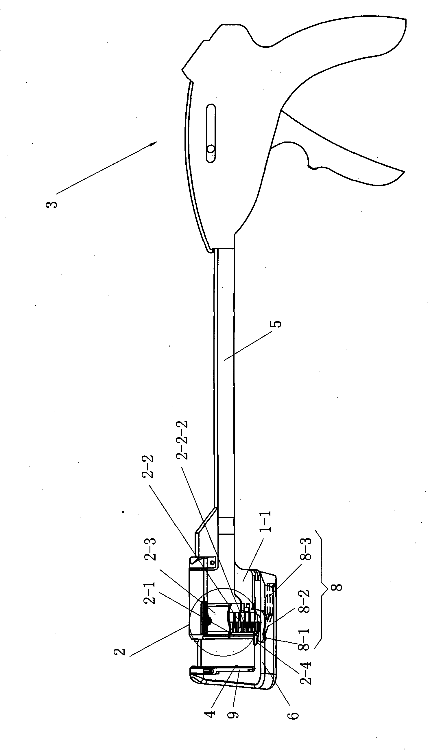
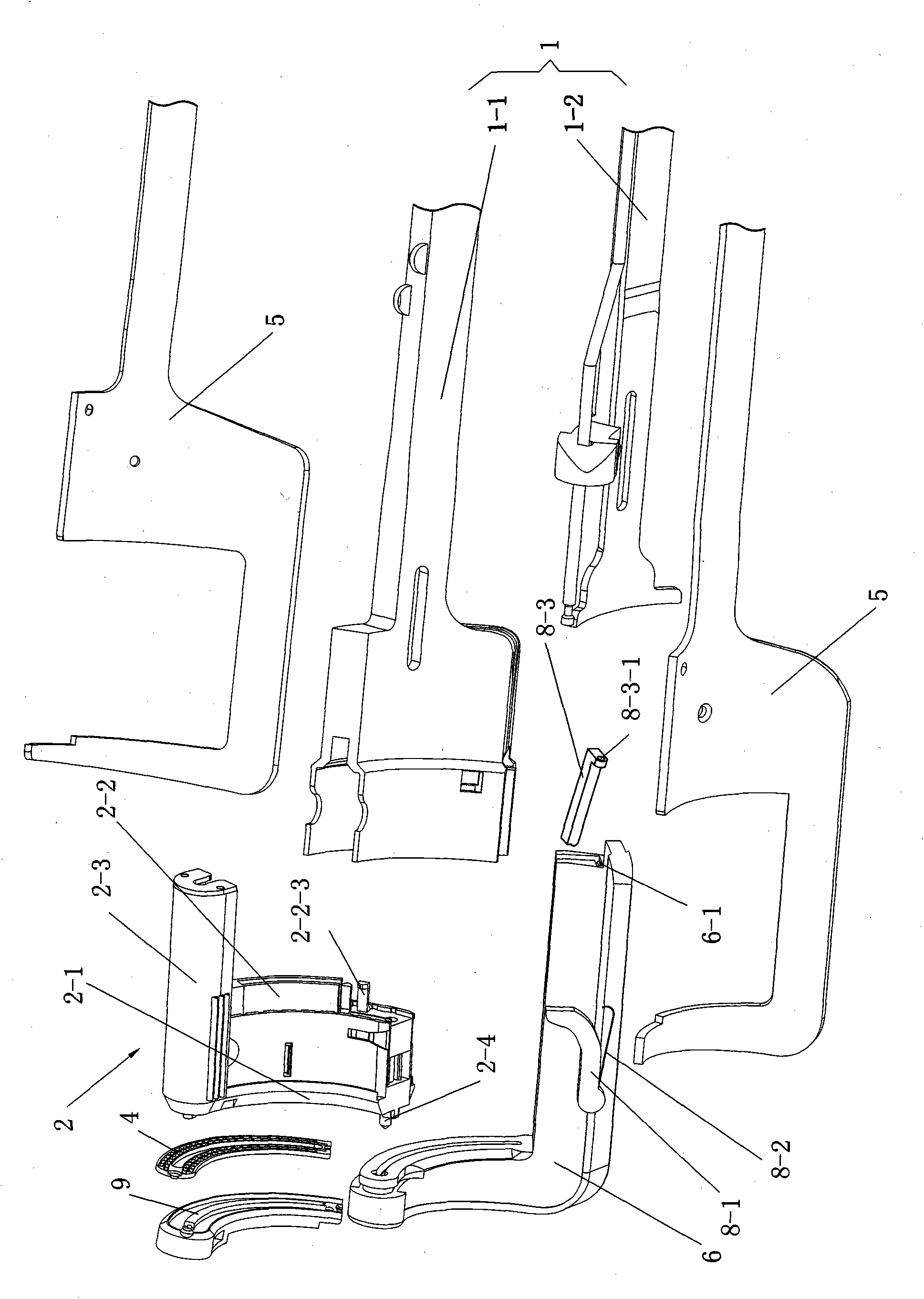
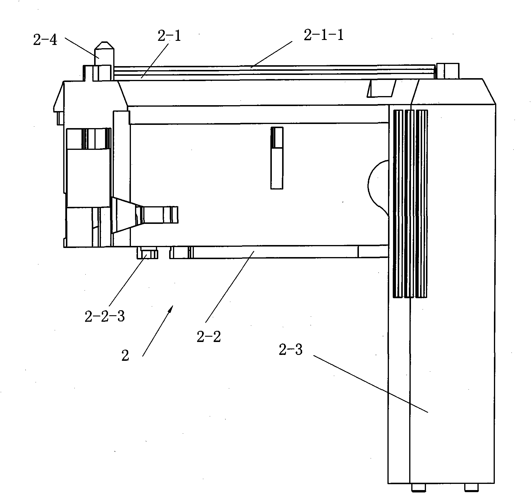
[0033] Such as Figure 1-19As shown, an arc-shaped cutting stapler includes a staple forming mechanism 1, a staple pusher assembly 2, a firing handle 3, an abutment seat 4, a base 6 of the abutment seat, a spacer ring 9 and two splints 5. The staple forming mechanism 1 includes a component bracket 1-1 and a pusher plate 1-2, the pusher plate 1-2 is inserted in the component bracket 1-1 and is slidably matched with the component bracket 1-1, and the firing handle 2 Drive connection with the component bracket 1-1 and nail pusher plate 1-2, and fixed connection with two splints 5, the nail anvil 4 is fixed on the spacer ring 9, and the spacer 9 is fixed on the base 6 of the nail anvil , the base 6 of the nail anvil is fixedly connected to the two splints 5, the nail pusher assembly 2 is mounted on the assembly bracket 1-1 and is opposit...


PUM


Abstract

The invention relates to an arc-shaped cutting anastomat comprising an anastomosis nail shaping mechanism, a nail pushing assembly, a trigger handle, a nail supporting seat, a base of the nail supporting seat, a knife cushioning ring and two splints, wherein the nail pushing assembly comprises a cutting knife, a nail pushing sheet, a nail bin and a guide post; the end of the nail pushing sheet and both sides of the cutting knife are respectively provided with a plurality of inner nail pushing dental sheets which are near the cutting knife and a plurality of outer nail pushing dental sheets which are far away from the cutting knife; the cutting knife and the nail pushing sheet are injected and molded at a time to be fixed together; the outer side of the each outer nail pushing dental sheet on the nail pushing sheet is provided with a reinforcing rib; the inner side of each nail pushing dental sheet on the nail pushing sheet is provided with a reinforcing rib; both ends of the first guide surfaces of the nail pushing dental sheets are respectively connected with the first contact surfaces and the second contact surfaces of the nail pushing dental sheets through concave arc-shaped connecting surfaces, and both ends of the second guide surfaces thereof are respectively connected with the first contact surfaces and the second contact surfaces through the concave arc-shaped connecting surfaces; and the first contact surfaces and the second contact surfaces are respectively in contact with the inner walls of the nail pushing dental sheet holes of the nail bin. The invention has the advantages of good trigger anastomosis shaping effect and high safety.

Description

technical field [0001] The invention belongs to the technical field of medical instruments, in particular to an arc cutting stapler. Background technique [0002] There are various types of staplers on the market, which are widely used in surgical operations to anastomose various parts of the human body, which can reduce operation time and improve operation quality. The anastomosis is firm and reliable, and the hemostatic effect is good. At present, the disposable curved cutting stapler is mainly suitable for low anterior rectal resection. There are certain disadvantages in the existing arc-shaped cutting stapler: first, the cutting knife is fixed on the knife seat, and the knife seat is fixedly connected with the pusher piece. The three of them need to move forward synchronously, because there is a gap between the assembled nail pusher and the knife seat, which will cause the movement of the nail pusher, cutting knife and knife seat to be out of sync or cause the cutting k...

Claims


Application Information

Patent Timeline
IPC IPC(8): A61B17/068
Inventor 李东瑞李翔
Owner CHANGZHOU JIANRUIBAO MEDICAL DEVICES
Why Eureka
Try Eureka