Fixed die core-pulling mechanism capable of self-locking and backstopping

A core-pulling mechanism and anti-retraction technology, applied in the field of fixed-mold core-pulling mechanism, can solve problems such as difficult to guarantee accuracy, difficult to control product quality, and decreased overall strength of fixed formwork

Inactive Publication Date: 2010-12-15
宁海县第一注塑模具有限公司
View PDF4 Cites 13 Cited by
  • Summary
  • Abstract
  • Description
  • Claims
  • Application Information

AI Technical Summary

Problems solved by technology

[0003] prior art, see Figure 4 , set an oblique long channel 03 on the back of the fixed formwork for oblique sliding core-pulling of the oblique core-pulling block. In and out movement; when the mold is closed and injected, the thrust of the oil cylinder prevents the retreat of the oblique core block due to the strong injection force; because the hydraulic oil has the characteristic of being compressed under pressure, the oblique core block works in the mold There will be a small amount of backward movement during the process, and the result is a step or flash on the surface of the injection molded product, which makes it difficult to control the quality of the product and the quality is difficult to be stable and consistent.
In addition, due to the need to set up and down the obliquely long through-slot 03 on the fixed formwork for oblique sliding core-pulling of the oblique core-pulling block, the overall strength of the fixed formwork is reduced, and the processing of the obliquely long through-slot 03 is difficult, and the accuracy is difficult to guarantee; these Comprehensive factors lead to unreliable mold work, prone to failures such as oblique core block jamming or fixed template cracking
Therefore, there are problems and deficiencies in the prior art, such as unreliable mold work, prone to failure, and unstable product quality.

Method used


Image

  • Fixed die core-pulling mechanism capable of self-locking and backstopping
  • Fixed die core-pulling mechanism capable of self-locking and backstopping
  • Fixed die core-pulling mechanism capable of self-locking and backstopping

Examples


Embodiment Construction

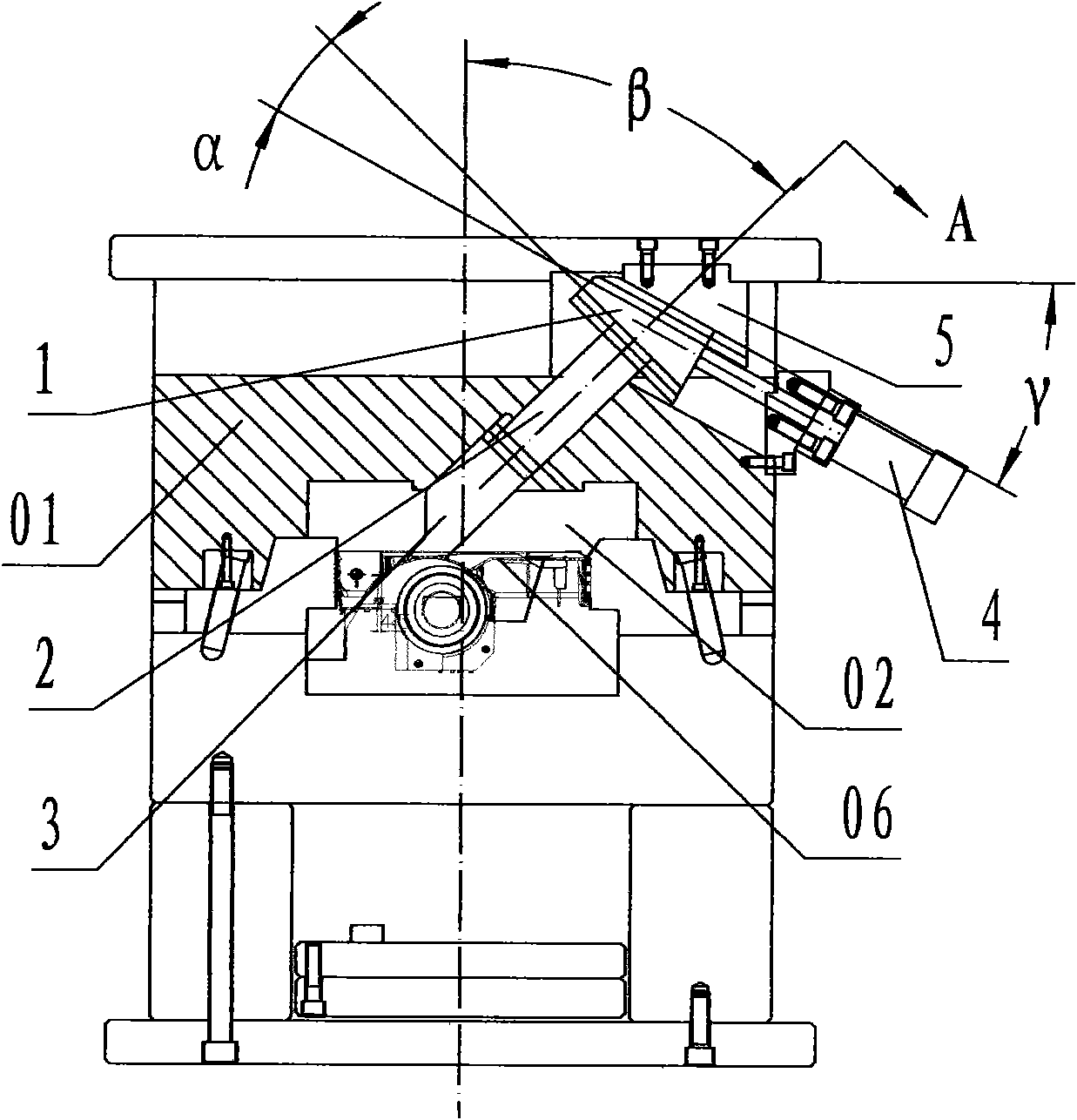
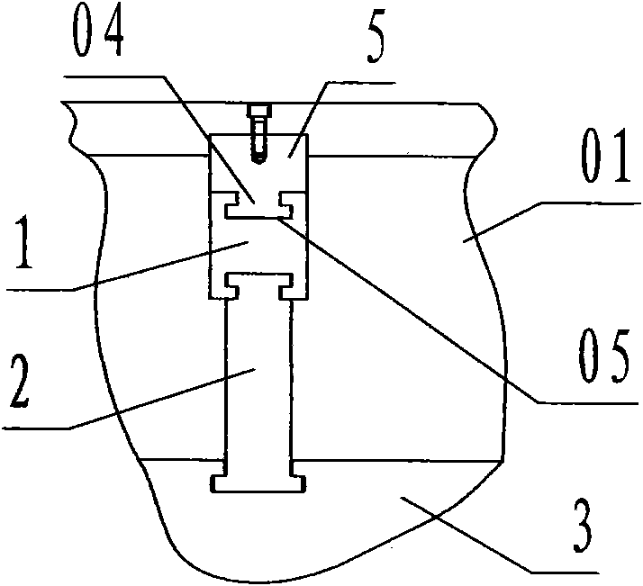
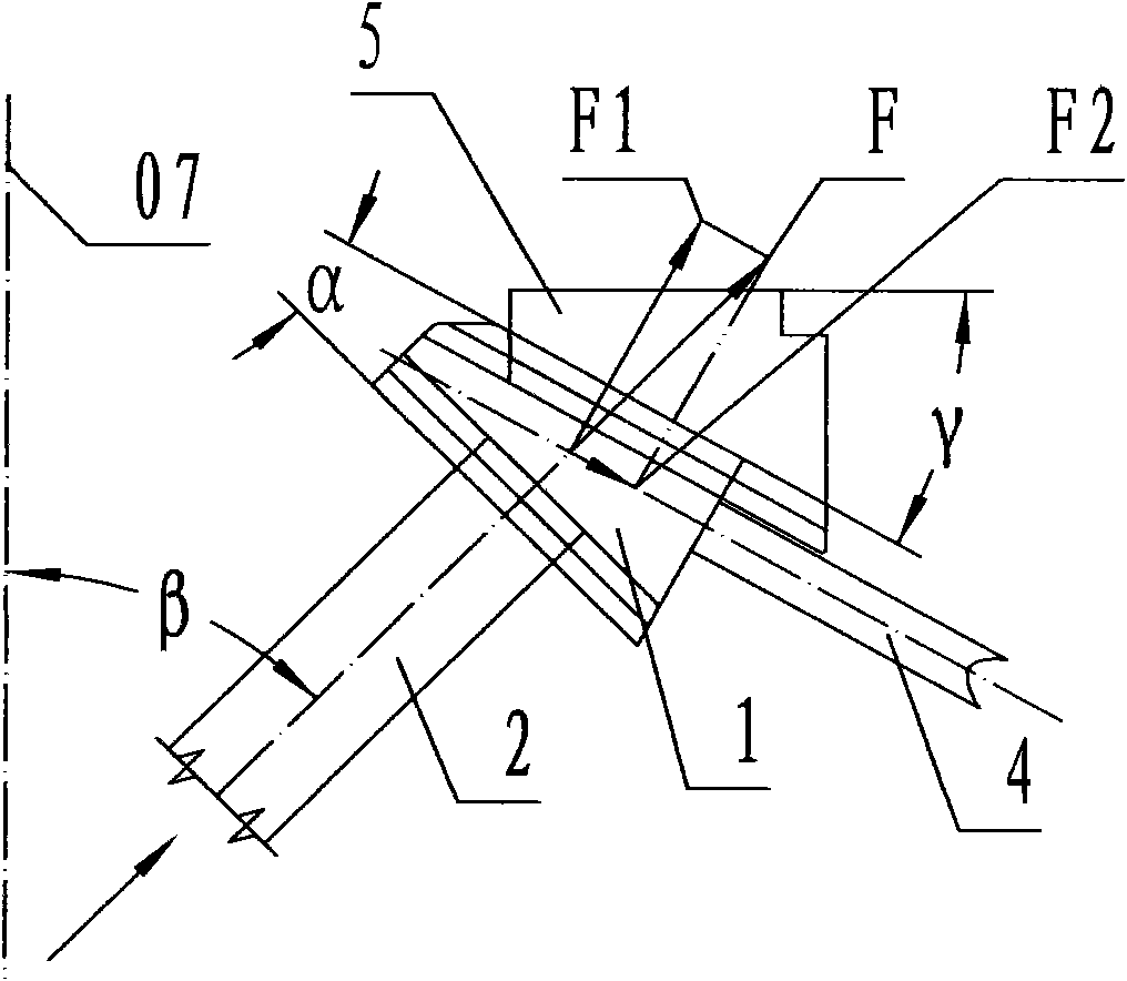
[0025] refer to Figure 1 ~ Figure 3 , a fixed-die core-pulling mechanism capable of self-locking and anti-retraction of the present invention, including a wedge-shaped slider 1, an inclined ejector rod 2, an inclined core-pulling block 3, an oil cylinder 4, and a support seat 5, wherein: the wedge-shaped slider 1 is a wedge shape with an angle of α between the upper and lower end faces along the long side direction, the side of the small end of the wedge is a plane orthogonal to the lower end face, the side of the big end of the wedge is a plane orthogonal to the upper end face, and the two long sides The side is a wedge-shaped steel block body that is orthogonal to the upper and lower end faces and parallel to each other; along the long side direction, the upper and lower end faces of the wedge-shaped slider are equipped with T-shaped slides with inverted T-shaped grooves in cross section. Groove 05; the value range of the α included angle is 12°~16°;

[0026] The inclined ...


PUM


Abstract

The invention discloses a fixed die core-pulling mechanism capable of self-locking and backstopping, which comprises a wedge-shaped sliding block (1), an oblique ejection rod (2), an oblique core-pulling block (3), an oil cylinder (4) and a support seat (5). By using the technical scheme that the oblique core-pulling block is connected with the wedge-shaped sliding block through the oblique ejection rod by using the frictional self-locking principle, and the oil cylinder is arranged obliquely so that the stressed included angle between the wedge-shaped sliding block and the oblique ejection rod is smaller than a frictional self-locking angle of the material, the mechanism overcomes the defects of unreliable work of a die, easy fault occurrence and instable product quality because the oblique core-pulling block retreats. In the fixed die core-pulling mechanism capable of self-locking and backstopping, the retreat of the oblique core-pulling block is prevented by the self-locking and backstopping effect of the wedge-shaped sliding block, and core pulling and resetting of the oblique core-pulling block with great retraction force are driven by the small-specification oil cylinder so that the injection molding die fulfills the purposes of reducing cost, obtaining reliable work, eliminating fault hidden dangers, stabilizing product quality and ensuring product quality consistency.

Description

technical field [0001] The present invention relates to a core-pulling mechanism of an injection mold, and specifically refers to a device used in a fixed mold of an injection mold to extract an oblique core-pulling block arranged at a cavity of a fixed mold from an injection molded product before the mold is opened. Fixed mold core-pulling mechanism with self-locking and non-retraction. Background technique [0002] Due to functional requirements, the internal structure of some injection molded products has structural features that cannot be demolded from the fixed mold cavity along the mold opening direction, so it is necessary to set a core-pulling mechanism in the fixed mold of the injection mold, for example, a wall-mounted air conditioner base There is a sink on the back of the mold, and it is a concave structure along the mold opening direction, so it is necessary to set a core-pulling mechanism in the fixed mold of the mold. [0003] prior art, see Figure 4 , set a...

Claims


Application Information

Patent Timeline
Patent Type & Authority Applications(China)
IPC IPC(8): B29C45/26
Inventor 顾初青
Owner 宁海县第一注塑模具有限公司
Why Eureka
Try Eureka