Low-pressure reciprocating mechanism of engineering machinery chassis

A technology of reciprocating motion mechanism and construction machinery, applied in mechanical equipment, engine components, engine sealing and other directions, can solve the problems of seal failure, the inner lip seal ring cannot be opened, leakage, etc., to ensure the sealing effect and prevent leakage. oil effect

Inactive Publication Date: 2010-12-15
XUANHUA CONSTR MACHINERY +1
View PDF8 Cites 5 Cited by
  • Summary
  • Abstract
  • Description
  • Claims
  • Application Information

AI Technical Summary

Problems solved by technology

However, when the operating temperature is low, the outer lip seal ring shrinks and its lip fits against the outer surface of the piston (see Figure 4 ), so that the hydraulic oil is not easy to enter the inner cavity of the outer lip seal ring, and the outer lip seal ring cannot be expanded, resulting in part of the hydraulic oil entering the hydraulic oil chamber leaking from the gap between the outer lip seal ring and the piston seat
Similarly, when the temperature of the working oil is high, the inner lip seal ring expands, and its lip fits the inner surface of the piston, making it difficult for hydraulic oil to enter the inner cavity of the inner lip seal ring (see Image 6 ), the inner lip seal ring cannot expand, resulting in seal failure

Method used


Image

  • Low-pressure reciprocating mechanism of engineering machinery chassis
  • Low-pressure reciprocating mechanism of engineering machinery chassis
  • Low-pressure reciprocating mechanism of engineering machinery chassis

Examples


Embodiment Construction

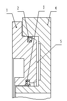
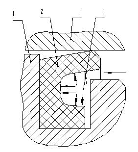
[0022] The invention overcomes the disadvantage of poor sealing effect of the lip seal ring of the low-pressure reciprocating mechanism of the existing engineering machinery chassis. When the working temperature is low or high, the hydraulic oil can also enter the lip of the lip seal ring, so that the lip seal ring up open.

[0023] The technical solution of the present invention is to process the oil guide groove (including the inner oil guide groove 9 and the outer oil guide groove 8) on the support element (that is, the piston 1) of the lip seal ring (including the inner lip seal ring 3 and the outer lip seal ring 2) ), so that the oil guide groove is connected with the seal ring groove (the inner oil guide groove 9 is connected with the inner seal ring groove 11, and the outer oil guide groove 8 is connected with the outer seal ring groove 10), so that the hydraulic oil in the hydraulic oil chamber 5 can be It directly enters the inner cavity 7 of the inner lip seal ring a...


PUM


Abstract

The invention discloses a low-pressure reciprocating mechanism of an engineering machinery chassis, which belongs to the technical field of engineering machinery and is used for improving the sealing effect of the reciprocating mechanism. The technical scheme of the reciprocating mechanism is that: the reciprocating mechanism comprises an annular piston and a piston seat, wherein the inner surface of the annular piston is provided with an inner sealing circular groove which is coaxial with the piston; an inner lip-shaped sealing ring is arranged in the inner sealing circular groove; the outer surface of the annular piston is provided with an outer sealing circular groove which is coaxial with the piston; an outer lip-shaped sealing ring is arranged in the outer sealing circular groove; after improvement, the inner surface of the piston is provided with an inner oil guide groove which is communicated with the inner sealing circular groove; the outer surface of the piston is provided with an outer oil guide groove which is communicated with the outer sealing circular groove; and both the inner oil guide groove and the outer oil guide groove are positioned in an annular hydraulic oil cavity which is formed by enclosing the piston, the piston seat, the inner lip-shaped sealing ring and the outer lip-shaped sealing ring. The low-pressure reciprocating mechanism of the engineering machinery chassis can ensure the sealing effect thereof under the high temperature working condition and the low temperature working condition and completely prevent the occurrence of oil leakage phenomenon.

Description

technical field [0001] The invention relates to a low-pressure reciprocating motion mechanism for a chassis of a hydraulic engineering machinery with good sealing effect and no hydraulic oil leakage, belonging to the technical field of engineering machinery. Background technique [0002] The low-pressure reciprocating mechanism is widely used in the chassis of construction machinery. The common reciprocating mechanism is composed of an annular piston and a piston seat (see figure 1 , figure 2 ), an inner sealing ring groove coaxial with the piston is arranged on the inner surface of the annular piston, an inner lip sealing ring is installed in the inner sealing ring groove, and an outer sealing ring groove coaxial with the piston is arranged on the outer surface, An outer lip seal ring is housed in the outer seal ring groove. Piston, piston seat, inner lip seal ring and outer lip seal ring form a closed hydraulic oil chamber. The hydraulic oil entering the hydraulic oil ...

Claims


Application Information

Patent Timeline
Patent Type & Authority Applications(China)
IPC IPC(8): F16J15/32F15B15/14F16J15/3236
Inventor 于庆超滑翔高继明
Owner XUANHUA CONSTR MACHINERY
Why Eureka
Try Eureka