Centrifugal force drive based drawing device for equipment in pipeline

A traction device and centrifugal force technology, applied in the direction of mechanical equipment, pipe components, pipes/pipe joints/fittings, etc., can solve the problems of failure, increase of traction of equipment in the pipe, limited frictional traction between wheels or mechanical legs and the inner wall of the pipe, etc. Improve the effect of movement, strong portability, easy to adjust the effect

Inactive Publication Date: 2010-12-15
NAT UNIV OF DEFENSE TECH
View PDF3 Cites 7 Cited by
  • Summary
  • Abstract
  • Description
  • Claims
  • Application Information

AI Technical Summary

Problems solved by technology

When the rope is used to directly pull the device in the pipe, if the pipe is too long or there are too many bends, the friction between the rope and the inner wall of the pipe will increase to an unacceptable level; , due to the limitation of the inner diameter of the pipe, the frictional traction between the wheel or the mechanical leg and the inner wall of the pipe is very limited. When impurities such as water and mud remain in the pipe, it is more likely to cause the traction device to fail to pull the equipment in the pipe

Method used


Image

  • Centrifugal force drive based drawing device for equipment in pipeline
  • Centrifugal force drive based drawing device for equipment in pipeline

Examples


Embodiment Construction

[0016] The present invention will be further described in detail below in conjunction with the accompanying drawings and specific embodiments.

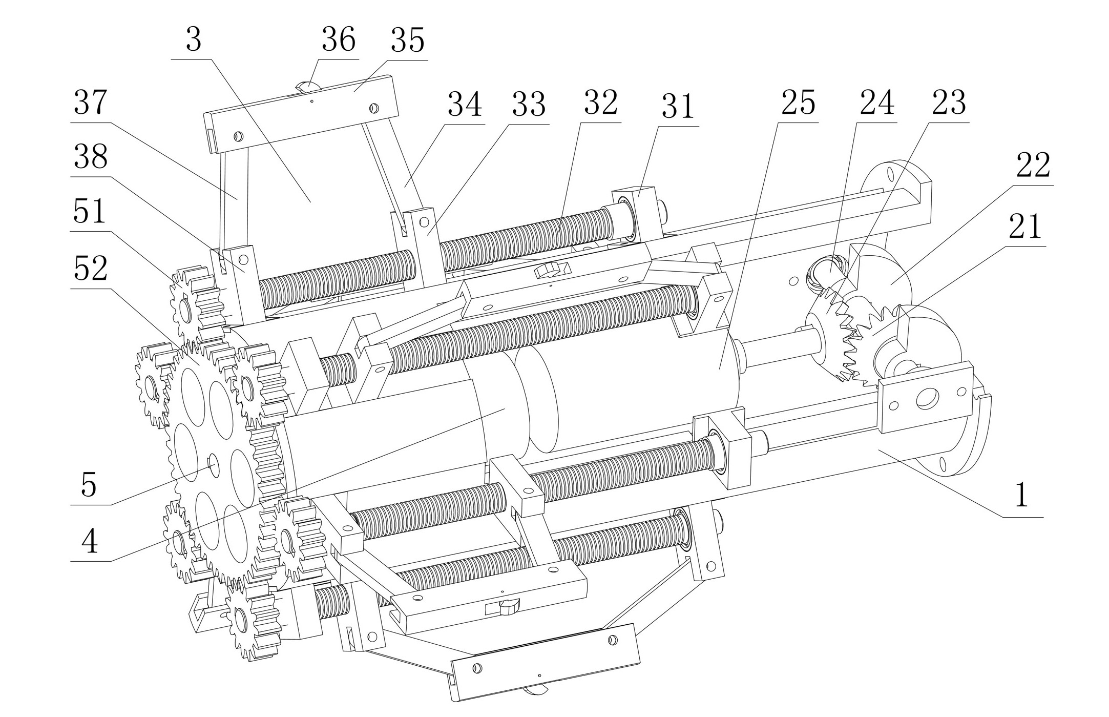
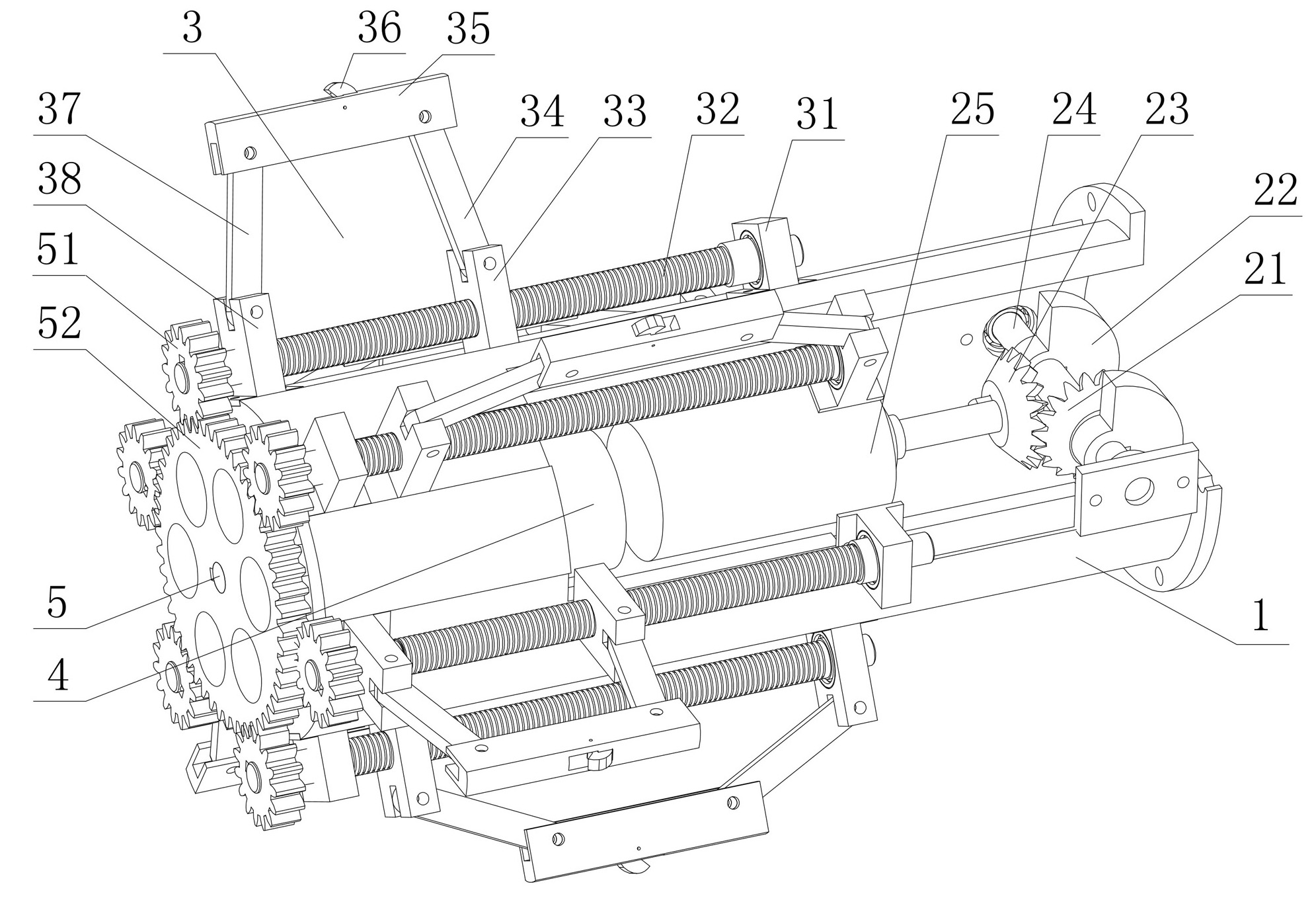
[0017] Such as figure 1 As shown, the in-pipe equipment traction device driven by centrifugal force of the present invention includes a bracket 1 sleeved in the pipeline and a centrifugal force generating mechanism and a motion locking mechanism fixed on the bracket 1. The centrifugal force generating mechanism includes a drive motor 25 and a transmission More than one set of eccentric mass rotating assemblies connected to the output end of the drive motor 25. The eccentric mass rotating assembly includes the eccentric mass rotating shaft 24 and the eccentric mass 22 fixed on the eccentric mass rotating shaft 24. The transmission mechanism is arranged in pairs and engaged with each other. The driving bevel gear 23 and the driven bevel gear 21, the driven bevel gear 21 is fixed on one end of the eccentric block rotating shaft 24, and t...


PUM


Abstract

The invention relates to a centrifugal force drive based drawing device for equipment in a pipeline, which comprises a bracket, a centrifugal force generating mechanism and a motion locking mechanism, wherein the bracket is sleeved in a pipeline; the centrifugal force generating mechanism comprises a drive motor and more than one set of eccentric block rotating assembly; the motion locking mechanism comprises an adjusting motor and more than four groups of connecting rod assemblies which are fixed on a stand along the circumferential direction of the pipeline; both ends of each screw rod in the connecting rod assemblies are respectively sleeved on a fixed rocker seat and a screw rod fixed seat; a floating rocker seat is sleeved on the screw rod by thread fit; one end of a fixed rocker is articulated on the fixed rocker seat, and the other end of the fixed rocker is connected with one end of a floating rocker by a connecting rod; the other end of the floating rocker is articulated on the floating rocker seat; a wedge block is fixed on the connecting rod; when the screw rods in all the connecting rod assemblies rotate towards the same direction, the motion directions of the floating rocker seats in the adjacent connecting rod assemblies are opposite. The invention has the advantages of simple and compact structure, low cost, stable and reliable work, wide application range, and the like.

Description

technical field [0001] The invention mainly relates to the design field of traction devices, in particular to a device for pulling various in-pipe equipment to move in a pipeline with a certain diameter range. Background technique [0002] With the development of economy and society, it is more and more important to use special instruments to detect, repair and measure various underground pipelines. At present, the methods commonly used at home and abroad to drive various equipment in the pipeline are to pass the rope in the pipeline in advance, pull the rope to pull the device in the pipeline to move inside the pipeline, or use various wheeled and legged small robots. The device in the pipe is driven by friction to move inside the pipe to complete various tasks such as detection and measurement in the pipe. When the rope is used to directly pull the device in the pipe, if the pipe is too long or there are too many bends, the friction between the rope and the inner wall of ...

Claims


Application Information

Patent Timeline
Patent Type & Authority Applications(China)
IPC IPC(8): F16L55/30
Inventor 潘存云徐海军易声耀李明宇徐小军高富东
Owner NAT UNIV OF DEFENSE TECH
Why Eureka
Try Eureka