
Method for carrying out centralized power supply on RACK system

A centralized power supply and power supply mode technology, applied in the direction of electrical components, circuit devices, emergency power supply arrangements, etc., can solve the problems of inability to deploy cabinets, achieve efficient monitoring and online maintenance, reduce power supply costs, and ensure uninterrupted power supply Effect

Active Publication Date: 2010-12-15
LANGCHAO ELECTRONIC INFORMATION IND CO LTD
View PDF5 Cites 32 Cited by
  • Summary
  • Abstract
  • Description
  • Claims
  • Application Information

AI Technical Summary

Problems solved by technology

As the amount of information increases, more cabinets cannot be deployed in the original computer room

Method used


Image

  • Method for carrying out centralized power supply on RACK system

Examples


Embodiment

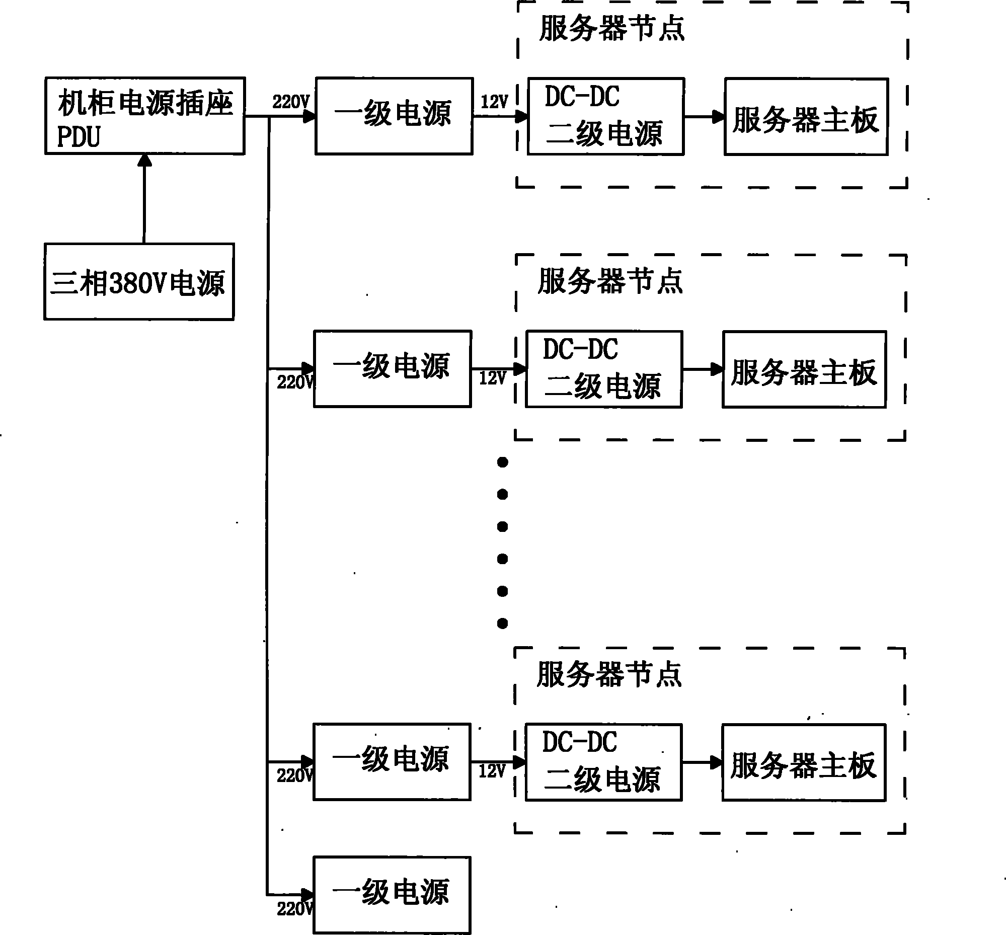
[0024] A method for centralized power supply of the RACK system of the present invention adopts the N+1 power supply module parallel redundant power supply mode and transfers the +12V power supply bus through the middle power supply backplane to supply power to the server nodes in the RACK system; two-stage power supply is adopted Power supply, the primary power supply adopts the parallel power supply mode of multiple power supply modules, that is, the parallel redundant power supply mode of N+1 power supply modules, to realize the conversion of 220V AC power supply to 12V DC power supply, and the 12V DC power supply is output to each server node in the RACK system; The on-board DC-DC secondary power supply of each server node converts the 12V power supply to provide the 12V, 5V, 3.3V, 5VSB, -12V voltage required by each server node and the timing signal of PS-ON and PowerGood switch; power supply The power module and the server node are connected together through the power bac...


PUM


Abstract

The invention discloses a method for carrying out centralized power supply on a RACK system and belongs to the technology in the field of power supply of server cabinet systems. Two stages of power supply are adopted to supply power. A primary power supply adopts a mode that a plurality of power supply modules are connected in parallel to supply power, namely a mode that N+1 power supply modules are connected in parallel to carry out redundant power supply. The method realizes conversion from a 220V AC power supply to a 12V DC power supply. The 12V DC power supply is output to each server node in the RACK system; an onboard DC-DC secondary power supply on each server node converts the 12V power supply and provides 12V, 5V, 3.5V, 5VSB and -12V required by various server nodes and sequence signals of the on-off of PS-ON and PowerGood. Compared with the prior art, the method for carrying out centralized power supply on the RACK system greatly improves the reliability of a power supply system, realizes connection without cables and is convenient to maintain.

Description

technical field [0001] The invention relates to a technology in the field of power supply for a server cabinet system, in particular to a method for centralized power supply to a RACK system. Background technique [0002] The rapid development of the Internet has resulted in explosive growth of information resources. People use the Internet as a media, and their demand for information is also increasing. Various large-scale data computer rooms have also emerged as the times require. The number of individuals—servers and storage cabinets—that make up a data center is also increasing. As the amount of information increases, more cabinets cannot be deployed in the original computer room. Therefore, the mobile container data room came into being. The power supply of the RACK (rack cabinet) system, the unit that makes up the mobile computer room, has become a difficult point. Contents of the invention [0003] The technical task of the present invention is to provide a cent...

Claims


Application Information

Patent Timeline
IPC IPC(8): H02J9/00G06F1/26
Inventor 滕学军罗嗣恒吴明生姚萃南
Owner LANGCHAO ELECTRONIC INFORMATION IND CO LTD
Learn More