Magnetic suspension flywheel energy storage device with suspension/energy storage integrated flywheel

A flywheel energy storage and magnetic levitation technology, which is applied in the field of flywheel energy storage, can solve the problems of energy loss, high cost of use, and complex structure of the magnetic levitation bearing system, and achieve the effects of weight reduction, energy density improvement, and simplified structure

Inactive Publication Date: 2010-12-15
NANJING UNIV OF TECH
View PDF4 Cites 23 Cited by
  • Summary
  • Abstract
  • Description
  • Claims
  • Application Information

AI Technical Summary

Problems solved by technology

[0009] Generally speaking, the flywheel in the existing magnetic levitation flywheel energy storage device is only used to store electric ener

Method used


Image

  • Magnetic suspension flywheel energy storage device with suspension/energy storage integrated flywheel
  • Magnetic suspension flywheel energy storage device with suspension/energy storage integrated flywheel

Examples


Embodiment Construction

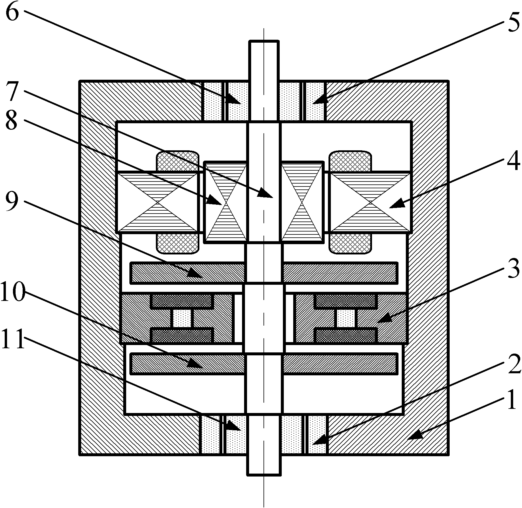
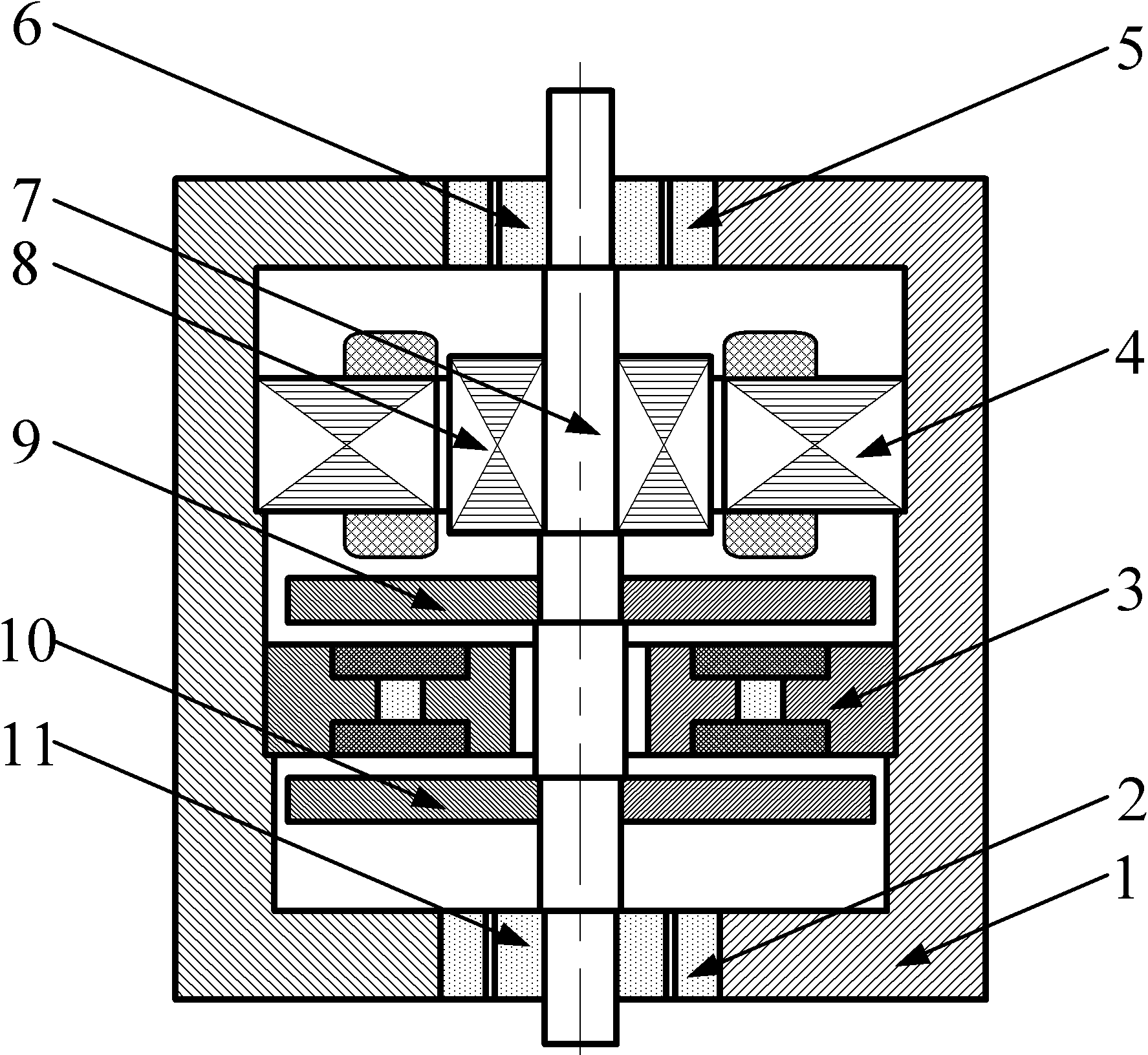
[0019] Such as figure 1 As shown, the permanent magnet type radial magnetic suspension bearing A stator 2 of the present invention, the electromagnetic permanent magnet hybrid axial magnetic suspension bearing stator 3, the motor / generator stator 4, and the permanent magnet radial magnetic suspension bearing B stator 5 are all set in the casing 1, its outer end faces are in contact with the inner end faces of the housing 1. Among them, the electromagnetic permanent magnet hybrid axial magnetic suspension bearing stator 3 is located between the permanent magnetic radial magnetic suspension bearing A stator 2 and the motor / generator stator 4, and the motor / generator stator 4 is located in the electromagnetic permanent magnetic hybrid axial magnetic suspension bearing Between the stator 3 and the permanent magnet type radial magnetic suspension bearing B stator 5. Permanent magnet radial magnetic suspension bearing B rotor 6, motor / generator rotor 8, suspension / energy storage in...


PUM

PropertyMeasurementUnit
Widthaaaaaaaaaa

Abstract

The invention relates to a magnetic suspension flywheel energy storage device with a suspension/energy storage integrated flywheel, which comprises a shell, a permanent magnet type radial magnetic suspension bearing A stator, a permanent magnet type radial magnetic suspension bearing B stator, an electromagnetic permanent-magnet hybrid type axial magnetic suspension bearing stator and a motor/generator stator, wherein the permanent magnet type radial magnetic suspension bearing A stator and the permanent magnet type radial magnetic suspension bearing B stator are respectively positioned on the bottom and top of the shell; the electromagnetic permanent-magnet hybrid type axial magnetic suspension bearing stator and the motor/generator stator are installed on the inner wall of the shell; the device also comprises a permanent magnet type radial magnetic suspension bearing B rotor, a motor/generator rotor, a suspension/energy storage integrated flywheel A, a suspension/energy storage integrated flywheel B and a permanent magnet type radial magnetic suspension bearing A rotor which are arranged on a main shaft from top to bottom; the suspension/energy storage integrated flywheel B is positioned between the permanent magnet type radial magnetic suspension bearing A stator and the electromagnetic permanent-magnet hybrid type axial magnetic suspension bearing stator; and the suspension/energy storage integrated flywheel A is arranged between the motor/generator stator and the electromagnetic permanent-magnet hybrid type axial magnetic suspension bearing stator. The invention has the advantages of compact structure, small size, light weight, high efficiency and high energy density.

Description

technical field [0001] The invention relates to a flywheel energy storage technology in electric energy storage technology, in particular to a magnetic levitation flywheel energy storage device adopting a suspension / energy storage integrated flywheel. Background technique [0002] The storage of electric energy can be divided into four types according to specific methods: electrochemical energy storage, electromagnetic energy storage, phase change energy storage and physical energy storage. Among them, electrochemical energy storage includes lead-acid battery energy storage, nickel-hydrogen battery energy storage, nickel-cadmium battery energy storage, lithium-ion battery energy storage, sodium-sulfur battery energy storage and flow battery energy storage, electromagnetic energy storage includes superconducting energy storage and supercapacitor energy storage, phase change energy storage includes ice cold storage energy storage, etc., physical energy storage includes pumped ...

Claims


Application Information

Patent Timeline
IPC IPC(8): H02K7/02H02K7/09H02N15/00F16C32/04
CPCY02E60/16F16C32/0478F16C2361/55
Inventor 张广明王德明梅磊
Owner NANJING UNIV OF TECH
Why Eureka
Try Eureka