Liquid crystal display device

A liquid crystal display device and liquid crystal technology, which are applied in static indicators, instruments, nonlinear optics, etc., can solve the problems of suppressing the reduction of viewing angle characteristics, and achieve the effect of good viewing angle characteristics and suppressing the reduction of transmittance.

Inactive Publication Date: 2010-12-15
SHARP KK
View PDF4 Cites 16 Cited by
  • Summary
  • Abstract
  • Description
  • Claims
  • Application Information

AI Technical Summary

Problems solved by technology

Therefore, in the liquid crystal display device 600C, by shielding dark lines from light, degradation of viewing angle characteristics is suppressed.

Method used


Image

  • Liquid crystal display device
  • Liquid crystal display device
  • Liquid crystal display device

Examples


Embodiment approach 1

[0078] Hereinafter, a first embodiment of the liquid crystal display device of the present invention will be described with reference to the drawings.

[0079] figure 1 It is a schematic diagram showing the liquid crystal display device 100A of the present embodiment. The liquid crystal display device 100A includes an active matrix substrate 200 , an opposing substrate 300 , and a liquid crystal layer 400 sandwiched between the active matrix substrate 200 and the opposing substrate 300 . The active matrix substrate 200 has pixel electrodes 210 supported on an insulating substrate 202 and an alignment film (first alignment film) 220 covering the pixel electrodes 210 . In addition, the counter substrate 300 has a counter electrode 310 supported on a transparent insulating substrate 302 , and an alignment film (second alignment film) 320 provided on the counter electrode 310 . The liquid crystal layer 400 is sandwiched between the alignment film 220 of the active matrix substr...

Embodiment approach 2

[0121] Hereinafter, a second embodiment of the liquid crystal display device of the present invention will be described.

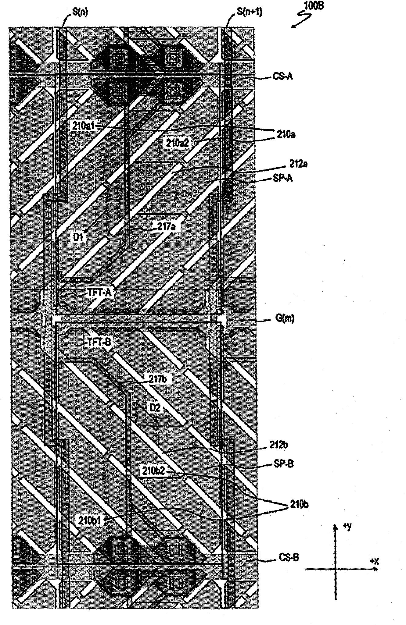
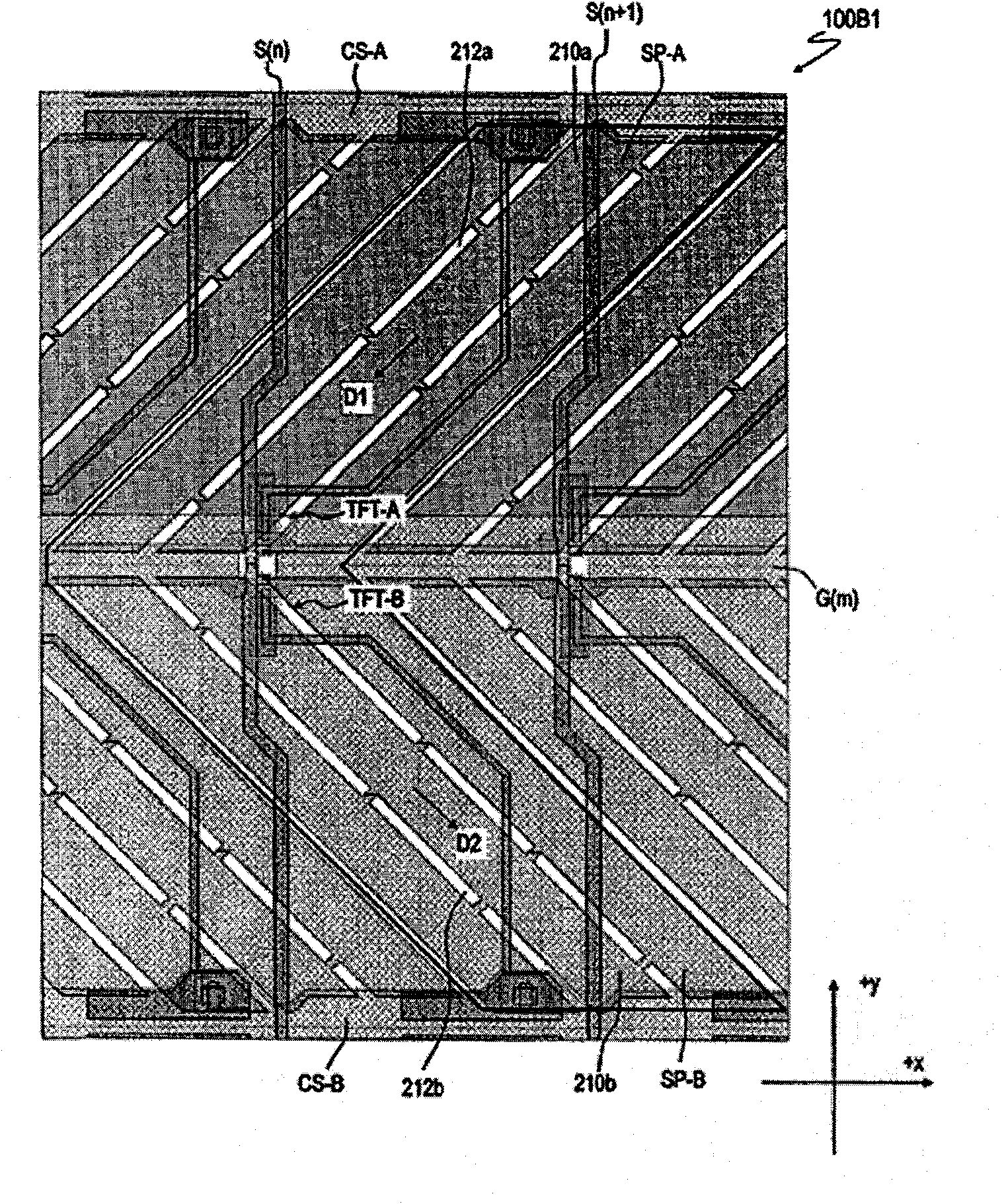
[0122] Figure 10 A schematic diagram of a liquid crystal display device 100B of this embodiment is shown. The liquid crystal display device 100B differs from the liquid crystal display device 100A in the following points: the liquid crystal display device 100B is an MVA mode liquid crystal display device using ribs and / or slits on sub-pixel electrodes and / or opposing electrodes as alignment limiting units. In addition, the schematic cross-sectional view and equivalent circuit diagram of the liquid crystal display device 100B are the same as those in figure 1 with figure 2The illustrated liquid crystal display device 100A is the same, and repeated description is omitted. Furthermore, in the liquid crystal display device 100B, figure 1 The illustrated alignment films 220, 320 are vertical alignment films.

[0123] Figure 10 A schematic plan view o...

Embodiment approach 3

[0142] Hereinafter, a third embodiment of the liquid crystal display device of the present invention will be described.

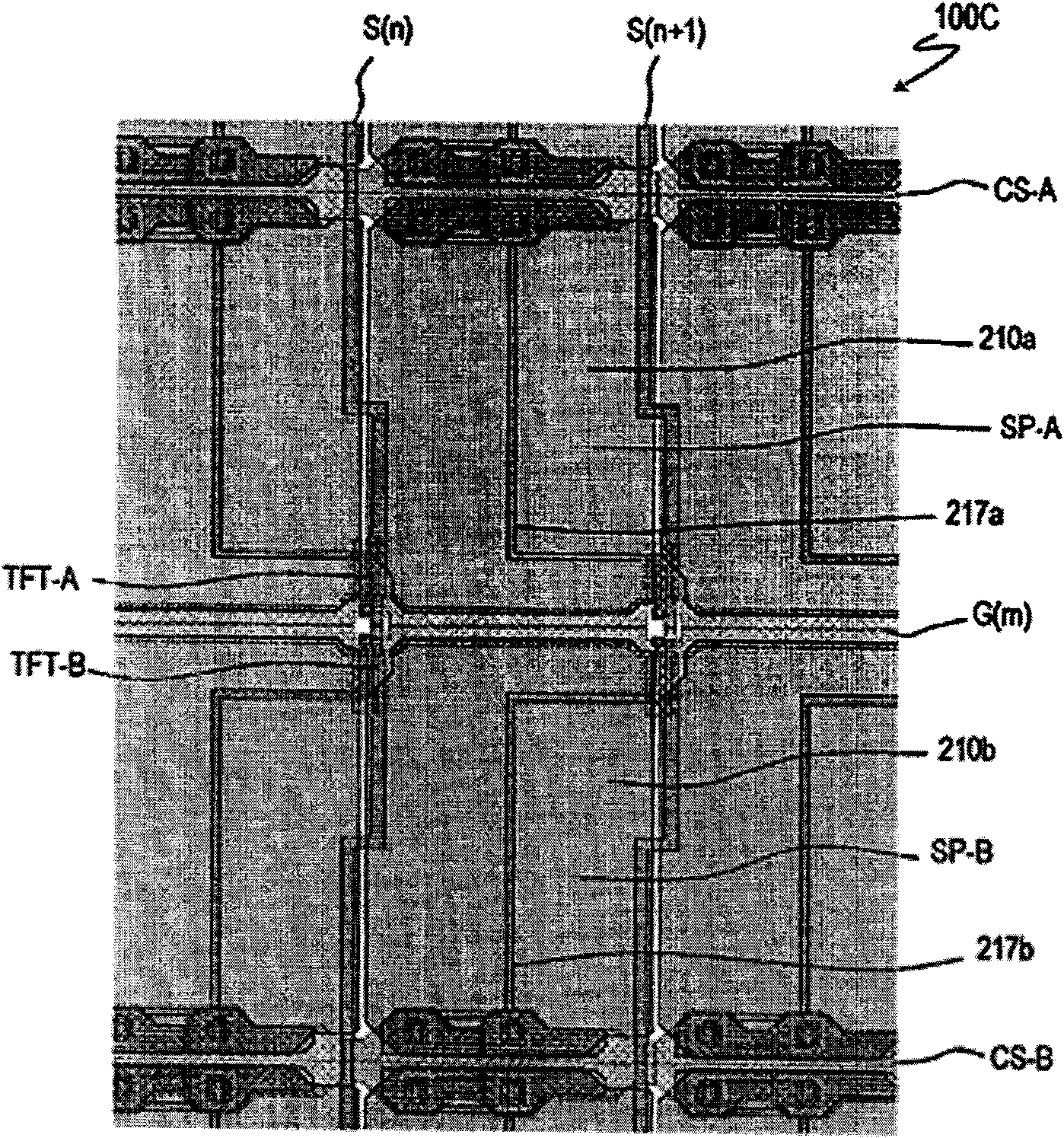
[0143] Figure 13A schematic diagram of a liquid crystal display device 100C of this embodiment is shown in . The liquid crystal display device 100C differs from the liquid crystal display devices 100A and 100B in the VA mode in that it is an OCB mode liquid crystal display device. The polarizing axes of the polarizers in the liquid crystal display devices 100A and 100B are parallel to the x-axis and the y-axis, while in the liquid crystal display device 100C, the polarizing axes of the polarizing plates cross the x-axis and the y-axis (typically, at 45°). way to set. In addition, the liquid crystal display devices 100A and 100B are normally black, and the liquid crystal display device 100C is normally white. The alignment regulating means in the liquid crystal display device 100C is an alignment film similarly to the liquid crystal display device 100A. ...


PUM


Abstract

A liquid crystal display device includes pixels including a first and a second sub pixel (SP-A, SP-B). Liquid crystal molecules in the liquid crystal layer of the first sub pixel (SP-A) are orientated in a first and a second reference orientation direction without being orientated in a third or a fourth orientation direction. Liquid crystal molecules in the liquid crystal layer of the second sub pixel (SP-B) are orientated in a third and a fourth reference orientation direction without being orientated in the first or the second direction. During a certain vertical scan period, the absolute value of effective voltage applied to the liquid crystal layer of the first sub pixel (SP-A) is greater than the absolute value of the effective voltage applied to the liquid crystal layer of the second sub pixel (SP-B). During another vertical scan period, the absolute value of effective voltage applied to the liquid crystal layer of the second sub pixel (SP-B) is greater than the absolute value of the effective voltage applied to the liquid crystal layer of the first sub pixel (SP-A).

Description

technical field [0001] The present invention relates to a liquid crystal display device. Background technique [0002] A liquid crystal display device is used not only as a small display device such as a display unit of a mobile phone but also as a large television. Conventional TN-mode liquid crystal display devices have relatively narrow viewing angles. Therefore, in recent years, widening viewing angles have been sought in liquid crystal display devices of various modes. [0003] An OCB (Optical Compensated Birefringence: Optically Compensated Birefringence) mode liquid crystal display device is known as a mode having a wider viewing angle than the TN mode. Figure 22 It is a schematic diagram showing a liquid crystal display device 600A in a normal OCB mode. in, Figure 22 The liquid crystal molecules in the middle liquid crystal layer 900 are in a bend alignment state. [0004] In the liquid crystal display device 600A, the two alignment films 720 and 820 facing each ...

Claims


Application Information

Patent Timeline
Patent Type & Authority Applications(China)
IPC IPC(8): G02F1/133G02F1/1337G02F1/139
CPCG09G2300/0443G09G3/3607G09G2310/06G02F1/133707G09G2300/0491G09G3/3614G09G3/3648
Inventor 中川英俊
Owner SHARP KK
Why Eureka
Try Eureka