Panel and panel installation structure

Inactive Publication Date: 2014-06-26
MITSUBISHI ENG PLASTICS CORP
View PDF1 Cites 35 Cited by
  • Summary
  • Abstract
  • Description
  • Claims
  • Application Information

AI Technical Summary

Benefits of technology

[0066]A panel body of a panel according to a first invention includes a laminate of at least a light-transmissive and light-absorbing heat-storing IR-absorbing layer and a light-transmissive heat-insulating layer, and thus radiation of the heat stored due to IR absorption by the IR absorbing layer can be inhibited by the heat-insulating layer. Therefore, for example, in application to automotive glazing, when the panel is mounted so that the IR-absorbing layer is disposed on the outside of a car and the heat-insulating layer is disposed on the interior side, radiation of the heat of the IR-absorbing layer at a temperature increased by IR absorption is shielded by the heat-insulating layer, thereby preventing an increase in the interior temperature of a car.
[0067]In addition, the panel according to the first invention further exhibits effects described below.
[0068](1) It is necessary to mix an IR absorber such as metal boride fine particles or the like with a thermoplastic resin composition used as a constituent material of the IR absorbing layer, and a molded product formed by molding the thermoplastic resin composition is inferior in characteristics, such as impact resistance, moisture-heat resistance, and the like, due to mixing of the IR absorber as compared with a molded product formed by molding a thermoplastic resin composition not containing the IR absorber. However, in the panel according to the present invention, the problem of deterioration in the characteristics due to t

Problems solved by technology

Glass with excellent thermal conductivity has the large effect of radiating heat outward from cars, while resins have low thermal conductivity and thus maintain the heat stored inside cabins due t

Method used


Image

  • Panel and panel installation structure
  • Panel and panel installation structure
  • Panel and panel installation structure

Examples


example 1

[0771]As described in Tables 2 and 3, a panel body as a test sample having a thickness configuration shown in Table 2 was formed by a method described below using PCII as a molding material of an IR-absorbing layer and PCI as a molding material of a heat-insulating layer.

[0772]First, PCII was injection-molded (cylinder temperature: 300° C.) in a cavity formed between a fixed mold and a movable mold which were controlled to a mold temperature of 80° C. to form an IR-absorbing layer (second layer). An injection rate was a single rate of 50 mm / sec, and a change-over position between injection and holding pressures was 2 mm. Molding was performed with a valve gate-type hot runner. Injection compression molding was performed, and the mold was opened by 2 mm before injection and was again clamped with 700 t at the injection-holding pressure change-over position. In this case, a holding time for mold re-clamping was 15 seconds. Then, after cooling for 60 seconds, the movable mold was opene...

example 2

[0774]A panel body as a test sample including an integral laminate of an IR-absorbing layer and a heat-insulating layer was molded by the same method as in Example 1 except that as described in Tables 2 and 3, PCIII was used as a molding material of the IR-absorbing layer, PCI was used as a molding material of the heat-insulating layer, and the cylinder temperature for molding was 320° C.

example 3

[0775]As described in Tables 2 and 3, a panel body as a test sample having a thickness configuration shown in Table 2 was formed by a method described below using PCV as a molding material of an IR-absorbing layer and PCI as a molding material of a heat-insulating layer.

[0776]First, PCI was injection-molded (cylinder temperature: 300° C.) in a cavity formed between a fixed mold and a movable mold which were controlled to a mold temperature of 80° C. to form the heat-insulating layer (first layer). An injection rate was a single rate of 50 mm / sec, and an injection-holding pressure change-over position was 2 mm. Molding was performed with a valve gate-type hot runner. Injection compression molding was performed, and the mold was opened by 2 mm before injection and was again clamped with 700 t at the injection-holding pressure change-over position. In this case, a holding time for mold re-clamping was 15 seconds. Then, after cooling for 60 seconds, the movable mold was opened to remove...


PUM

PropertyMeasurementUnit
Fractionaaaaaaaaaa
Fractionaaaaaaaaaa
Thicknessaaaaaaaaaa

Abstract

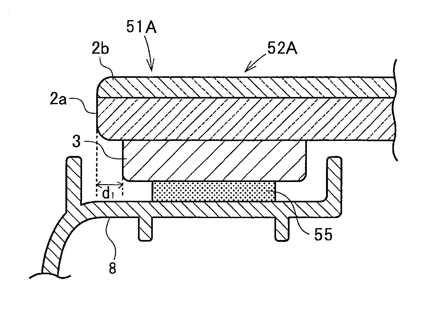
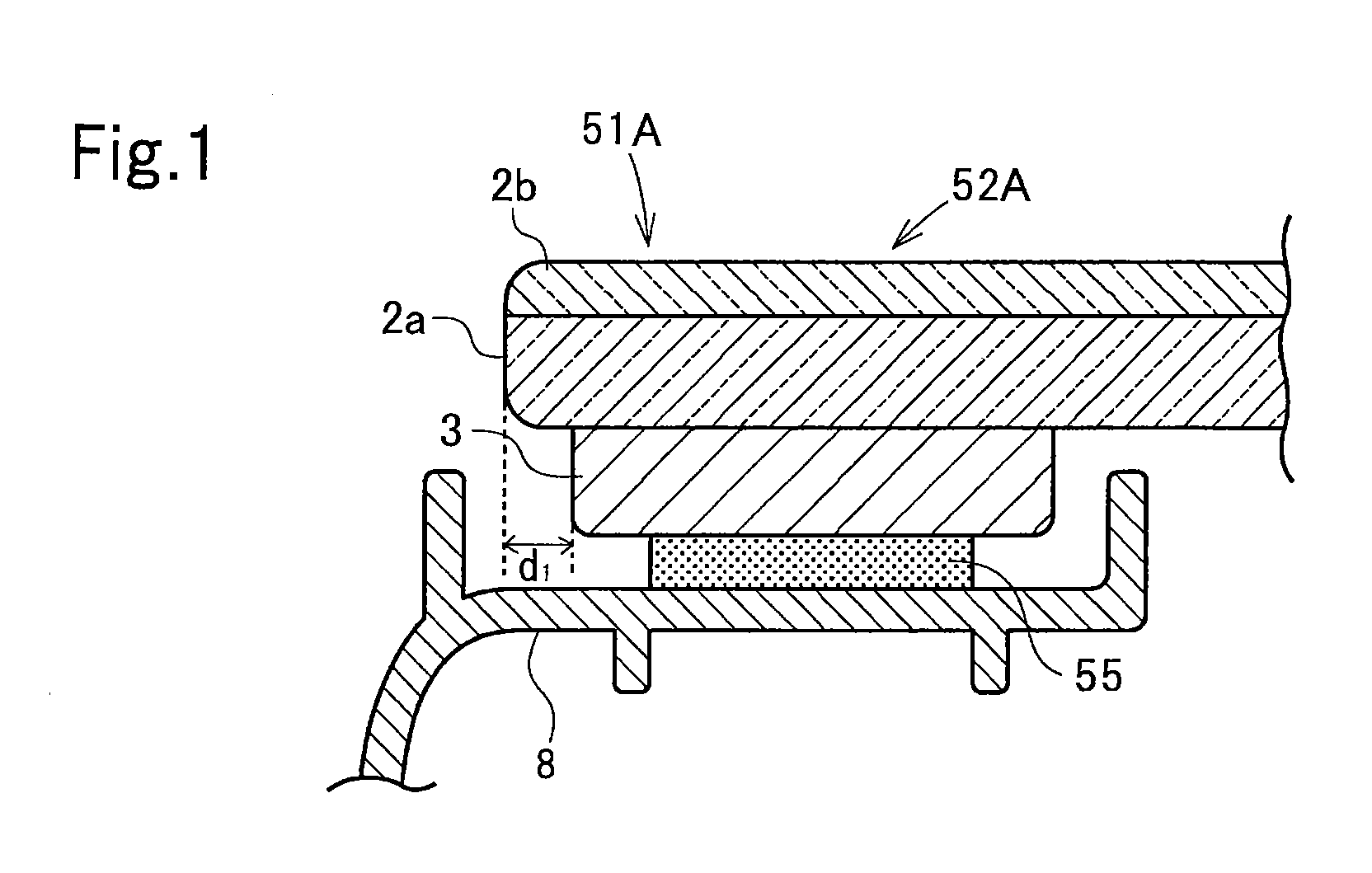
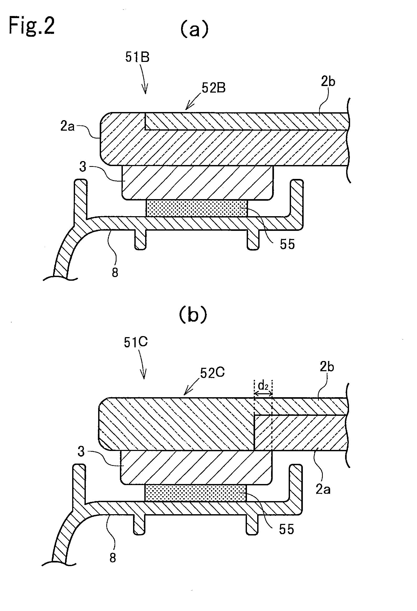
The present invention provides a panel having a light-absorbing heat-storing panel body in which the problem of heat storage with light absorption by the panel body is reduced. A panel 51A includes a panel body 52A made of a thermoplastic resin and having light transmissivity and the light-absorbing heat-storing property of absorbing light, converting the light to heat, and storing the heat therein. The panel body 52A has a laminated structure including a light-transmissive first layer 2a and a light-transmissive second layer 2b laminated on the first layer 2a and having the higher light-absorbing heat-storing property than the first layer 2a. The light-absorbing heat-storing panel body 52A has a laminated structure including at least two layers of the layer 2b that contributes to IR absorption and the layer 2a that serves as a heat-insulating layer so that radiation of the heat stored due to IR absorption by the layer 2b contributing to IR absorption can be shielded by the heat-insulating layer 2a, and thus a temperature rise due to radiant heat from the panel body 52A can be prevented.

Description

FIELD OF INVENTION[0001]The present invention relates to a panel suitably used as a window member for automotive cars and the like, and particularly to a panel using a transparent panel body having near-infrared to infrared absorptivity, in which the problem of heat storage with near-infrared to infrared absorption of the panel body is reduced.[0002]The present invention also relates to a vehicle including the panel.[0003]The present invention further relates to an installation structure of the panel and to a vehicle including the panel.BACKGROUND OF INVENTION[0004]In recent years, in the automotive field etc., various researches have been made of resin windows (glazing) alternative to glass for the purpose of reducing weights.[0005]Glazing is generally composed of a transparent window portion (a panel body according to the present invention) and a peripheral window frame (a frame member according to the present invention) and is generally produced by integrally molding the window p...

Claims


Application Information

Patent Timeline
IPC IPC(8): B60J1/00B32B7/023B32B7/027
CPCB60J1/007B60J1/008B32B27/365B32B2250/02B32B2307/40B32B2307/4026B32B2307/412B32B7/12B32B15/08B32B27/08B32B27/20B32B27/34B32B27/36B32B3/30B32B2307/304B32B2307/414B32B2419/06B32B2605/003B32B2605/08B29L2031/778B29L2007/002B29L2012/00B29K2995/0021B29K2995/0013B29C45/14336B29K2055/02B29K2067/00B29K2069/00B29K2077/10B29L2009/00B29K2995/0026B29L2031/30B29C48/92B29C48/07B29C48/0021B29C48/154B29C48/21B29C2948/92152B29C2948/92257B29C2948/92447B29C2948/92647B29C2948/92752B29C2948/92942Y10T428/24331Y10T428/24628Y10T428/24942Y10T428/2495Y10T428/24777Y10T428/24612B32B7/023B32B7/027
Inventor IMAIZUMI, HIROYUKINAGANO, FUMISATOTAKAHASHI, KAZUYUKI
Owner MITSUBISHI ENG PLASTICS CORP
Why Eureka
Try Eureka