Method and device for high-temperature combustion using fuel and aqueous solution of organic compound

a technology of organic compound and combustion method, which is applied in the direction of combustion types, lighting and heating apparatus, incinerator apparatus, etc., can solve the problem of difficult to expect a significant increase in combustion efficiency, and achieve the effect of reducing the cost of fuel

Inactive Publication Date: 2012-12-06
ISHIGURO SABURO +2
View PDF3 Cites 0 Cited by
  • Summary
  • Abstract
  • Description
  • Claims
  • Application Information

AI Technical Summary

Benefits of technology

[0016]According to the invention, in a combustion chamber, a fuel is sprayed and burned with a first burner to elevate the interior temperature of the combustion chamber to a high temperature of 700° C. or above, and an aqueous solution of an organic compound is subsequently sprayed with a second burner into the high-temperature combustion gas obtained with the first burner, consequently causing mixing and burning. Thus, compared to a case in which combustion is carried out by using only fuels or an aqueous solution of an organic compound, interior temperature of the combustion chamber and / or temperature of a chamber for heat treatment can be synergistically increased to high temperature. As such, the fuels and organic compounds are fully burned, and thus the fuel cost can be reduced.

Problems solved by technology

First, with regard to the condition at which water vapor microexplosion occurs, it involves instantaneous temperature increase of an organic aqueous solution to high temperature, and for example, water vapor microexplosion is caused by collision on surface of a solid at high temperature.
If no water vapor microexplosion occurs, only a simple aqueous gas reaction of water vapor and organic compounds contained in an organic aqueous solution and an oxidation reaction of air will occur, and therefore it is difficult to expect a significant increase in combustion efficiency.

Method used


Image

  • Method and device for high-temperature combustion using fuel and aqueous solution of organic compound
  • Method and device for high-temperature combustion using fuel and aqueous solution of organic compound
  • Method and device for high-temperature combustion using fuel and aqueous solution of organic compound

Examples


example 1

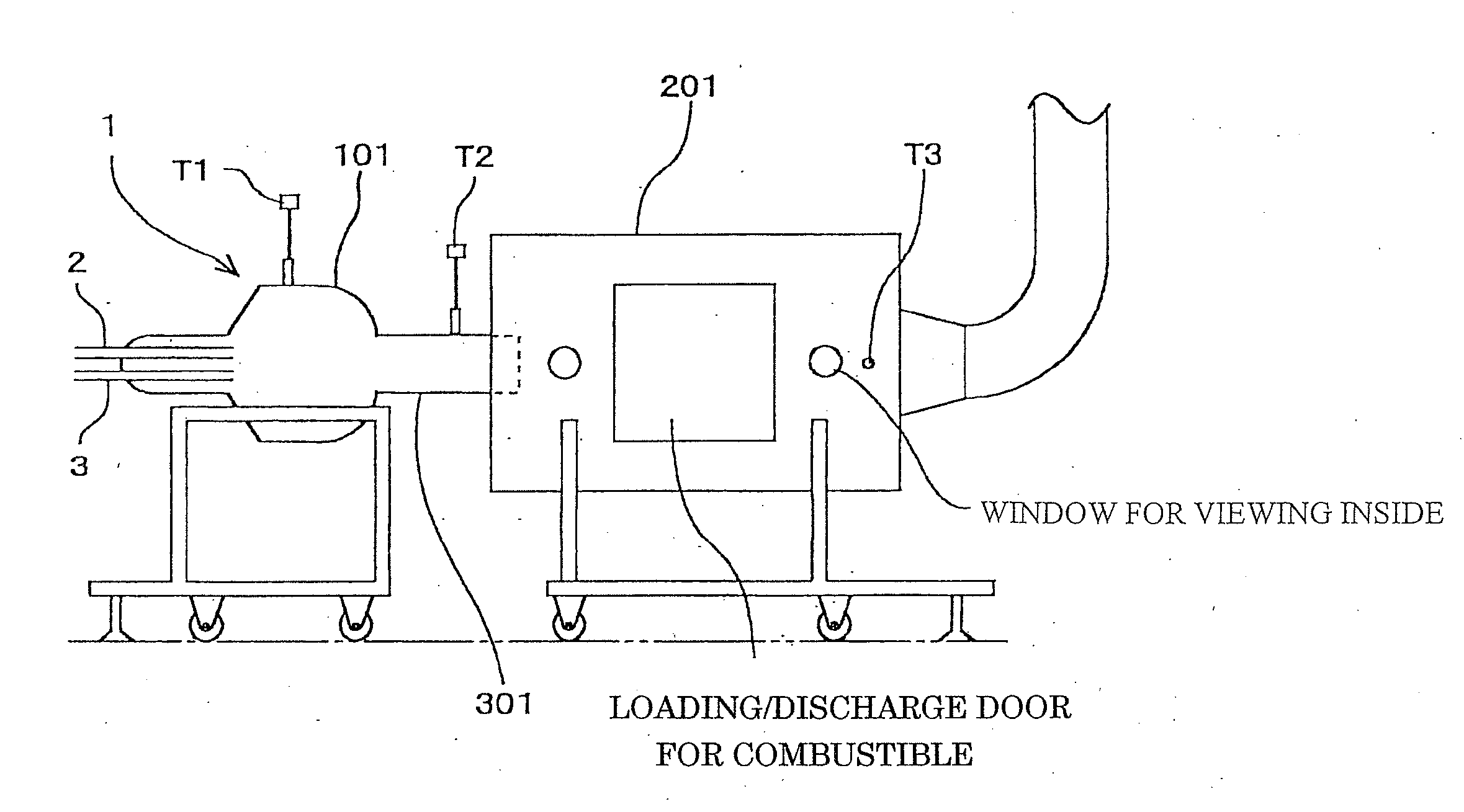
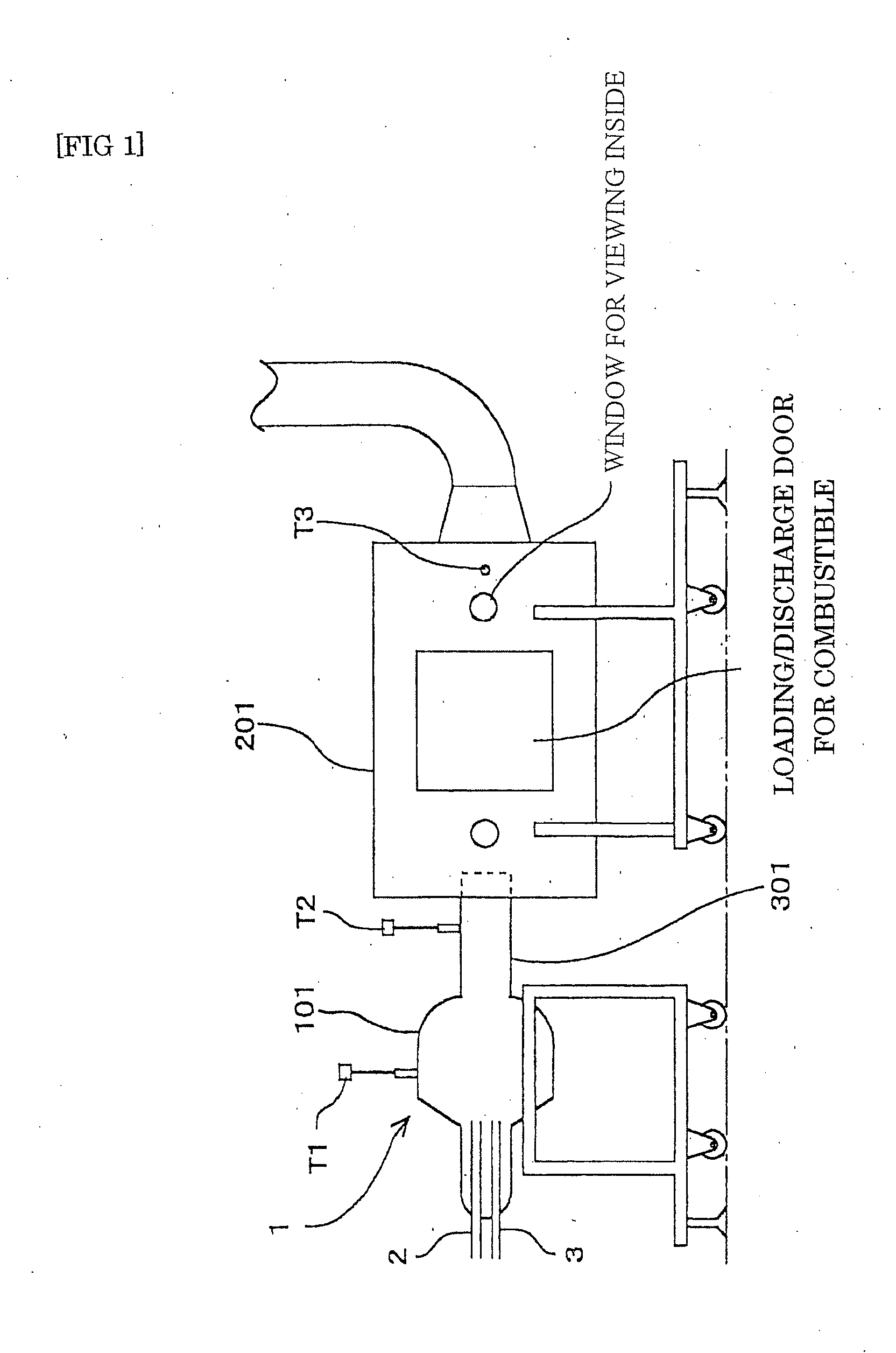
[0043]In this example, a device having a combustion chamber 1 to which a chamber for heat treatment 201 is connected is used as illustrated in the frontal view of FIG. 1.

[0044]Specifically, the combustion chamber 1 and the chamber for heat treatment 201 are connected to each other via a pathway 301 with reduced diameter, which connects an exit of the combustion chamber 1 and an entrance of the chamber for heat treatment 201.

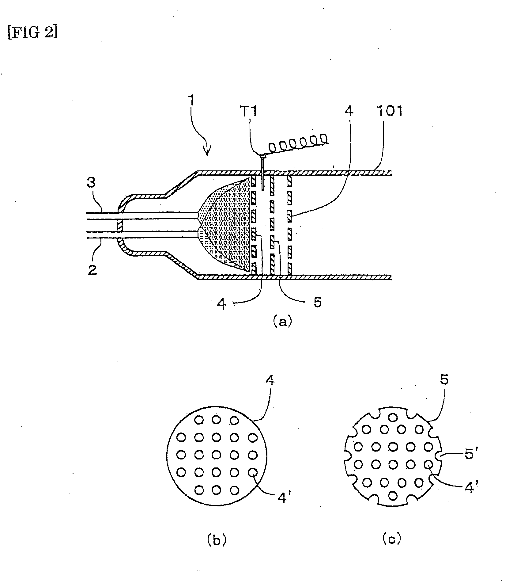
[0045]Further, in the combustion chamber 1, a first burner 2 for elevating the interior temperature to a high temperature of 700° C. or above and a second burner 3 for spraying an aqueous solution of an organic compound are installed.

[0046]Further, thermometers are placed at three spots in the device, that is, a first thermometer T1 is placed in the combustion chamber 1, a second thermometer T2 is placed in the pathway 301, and a third thermometer T3 is placed in the chamber for heat treatment 201.

[0047]Meanwhile, the chamber for heat treatment 201 is a place for...

example 2

[0057]Next, another example is explained.

[0058]First, heavy oil A was sprayed at 6.6 L / H (5.7 kg / H) from a first burner 2 to heat a combustion chamber 1. After heating for about one hour, temperature of a chamber for heat treatment 201 was 630° C. as measured by T3.

[0059]When 30% by volume aqueous ethanol solution (ethanol 4.6 L+water 10.6 L) was sprayed at 15.2 L / H by using a second burner 3, temperature of the chamber for heat treatment 201 as measured by T3 showed an increase of 190° C. from 630° C. to 820° C.

[0060]For the comparison, instead of 30% by volume aqueous ethanol solution, the same amount of pure ethanol was added and sprayed at 4.6 L / H by using the second burner 3, and as a result, temperature of the chamber for heat treatment 201 showed an increase of only 130° C., i.e., from 630° C. to 760° C.

[0061]The results are illustrated in FIG. 4.

[0062]Since the chamber for heat treatment 201 is used as a heating device for actual industrial use, the temperature increase in t...

example 3

[0069]The test was carried out in the same manner as Example 2 for 30% by volume aqueous methanol solution and pure methanol in the same amount.

[0070]The results are illustrated in FIG. 6.

[0071]By using the device illustrated in FIG. 1, heavy oil A was sprayed at 6.6 L / H from a first burner 2 into a combustion chamber 1 and heated. After heating for 1 hour, a thermometer T2 in the pathway connecting the exit of a combustion chamber reached 800° C. and exhibited an almost stable state. Thus, 30% by volume aqueous methanol solution was sprayed at 15.2 L / H (pure methanol 4.6 L / H and water 10.6 L / H) from a second burner 3. After 20 minutes, the thermometer T2 in the pathway connecting the exit of a combustion chamber showed 940° C., indicating a temperature increase of 140° C. while a thermometer T3 in a chamber for heat treatment showed a temperature increase of 130° C., i.e., from 630° C. to 760° C.

[0072]Meanwhile, for the comparison, pure methanol was sprayed at 4.6 L / H by using the ...


PUM


Abstract

A method and a device are disclosed with which high-temperature combustion is attained using a fuel and an aqueous solution of an organic compound, e.g., an aqueous alcohol solution. In a combustion chamber, a fuel is sprayed and burned with a first burner to elevate the interior temperature of the combustion chamber (and/or a heat-resistant reflector disposed inside the combustion chamber) to a high temperature of 700° C. or above, and an aqueous solution of an organic compound (e.g., an alcohol-water mixture) is subsequently sprayed with a second burner into the high-temperature combustion gas obtained with the first burner, thereby causing microexplosion of water vaper and further elevating the interior temperature. As such, the fuels and organic compounds (e.g., Alcoholic aqueous solution) are fully burned, and thus the fuel cost can be reduced. Thus, high-temperature superheated steam containing a large amount of water vapor is yielded.

Description

BACKGROUND OF THE INVENTION[0001]1. Field of the Invention[0002]The present invention relates to a method and a device for combustion of an aqueous solution of an organic compound. In particular, it relates to a method and a device for high-temperature combustion in which an aqueous solution of an organic compound like an aqueous alcohol solution and fuel are used.[0003]2. Description of the Related Art[0004]With regard to a conventional method for combustion by using liquid fuel and adding hydrous fuel containing an organic compound, examples of the organic compound for an aqueous solution of an organic compound (hereinbelow, referred to as an “organic aqueous solution”) include alcohols, organic acids, and aldehyde ketones. Examples of the organic aqueous solution include organic waste water, which is an industrial waste.[0005]For combustion of an organic aqueous solution, a common practice includes that an organic aqueous solution is slowly added thereto for combustion while heav...

Claims


Application Information

Patent Timeline
Patent Type & Authority Applications(United States)
IPC IPC(8): F23J7/00
CPCF23C2900/9901F23G5/085F23G5/12F23G5/46F23G5/50F23M9/06F23G7/008F23G2204/103F23G2206/20F23G2207/101F23G2900/50006F23G7/001F23G7/04
Inventor ISHIGURO, SABUROISHII, YUKIOMITAKE, KAZUTOSHI
Owner ISHIGURO SABURO
Why Eureka
Try Eureka