Liquid crystal device

A technology of a liquid crystal display device and a liquid crystal layer, applied in optics, instruments, nonlinear optics, etc., can solve the problems of not improving the reflection efficiency of the reflector 70, increasing the brightness of bright display, increasing the brightness of dark display, etc., and achieving high luminance The effect of improving brightness and contrast, and improving reflectivity

Inactive Publication Date: 2003-03-05
ALPS ALPINE CO LTD
View PDF0 Cites 3 Cited by
  • Summary
  • Abstract
  • Description
  • Claims
  • Application Information

AI Technical Summary

Problems solved by technology

However, in such a transflective liquid crystal display device, since only one retardation plate and a polarizing plate are simply reduced, and the reflection efficiency of the reflector 70 is not improved, not only increases the number of bright display (white display) ) brightness, also increases the brightness of the dark display (black display), so there is a problem of low contrast

Method used


Image

  • Liquid crystal device
  • Liquid crystal device
  • Liquid crystal device

Examples


experiment example 1

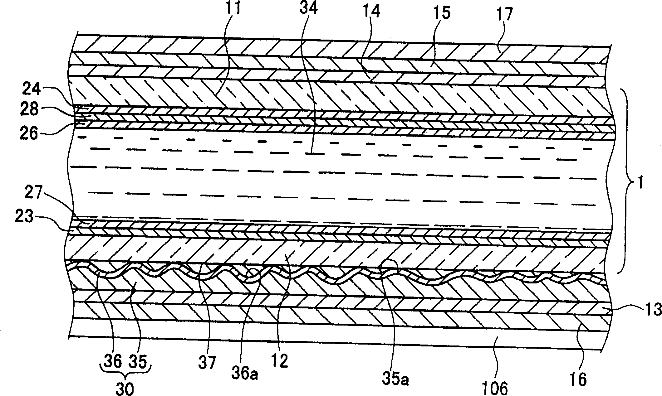
[0168] right Figure 1 to Figure 6 The display characteristics of the transflective liquid crystal display device of the illustrated embodiment in the reflective mode were tested.

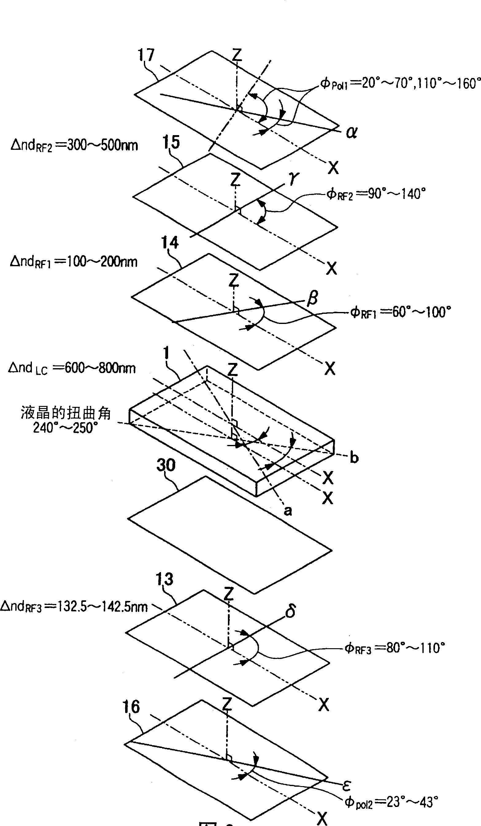
[0169] Here, PSI-2501 (trade name; manufactured by Chisso Corporation) was used as the upper and lower alignment films constituting the liquid crystal cell, and alignment treatment was performed so that the twist angle of the liquid crystal was 240 degrees. The angle between the alignment direction a of the upper alignment film and the above-mentioned normal direction X here is +330 degrees (-30 degrees) viewed from the incident side of the light, and the alignment direction b of the lower alignment film and the above-mentioned normal direction The angle formed by X is +30 degrees as viewed from the light incident side. As the liquid crystal of the liquid crystal layer, AP-4365LF (trade name; manufactured by Chisso Petrochemical Corporation) was used. NRZ-170 (trade name; manufactured by Nitto De...

experiment example 2

[0178] The display characteristics of the transflective liquid crystal display device of Sample No. 4 as an example were tested as follows.

[0179] Here, with respect to the display characteristics, it was measured that in the direction where the azimuth angle is 330 degrees with respect to the liquid crystal cell, the image 3 In the Z direction (the direction perpendicular to the incident side surfaces of the liquid crystal cell 1, the first retardation plate 14, the second retardation plate 15, and the first polarizing plate 17 respectively) at an incident angle of 15 degrees, the incident light from the light source Reflectance and contrast of emitted light (optical path 22mm, beam 500 lux). The result is as Figure 15 and Figure 16 shown.

[0180] Figure 15 It is a graph showing the relationship between the observation angle (light receiving angle) and the reflectance when light is incident at an incident angle of 15 degrees in the transflective liquid crystal disp...

experiment example 3

[0189] right Figure 1 to Figure 6 The display characteristics in the transmissive mode of the transflective liquid crystal display device of the illustrated embodiment were tested.

[0190] As the upper and lower alignment films constituting the liquid crystal cell here, PSI-2501 (trade name; manufactured by Chisso Corporation) was used, and alignment treatment was performed to make the twist angle of the liquid crystal 240 degrees. The angle formed by the alignment direction a of the upper alignment film and the above-mentioned normal direction X here is +330 degrees (-30 degrees) seen from the incident side of the light, and the alignment direction b of the lower alignment film and the above-mentioned normal direction X The formed angle is +30 degrees as viewed from the light incident side. As the liquid crystal of the liquid crystal layer, AP-4365LF (trade name; manufactured by Chisso Petrochemical Corporation) was used. As the first and second retardation plates, NRZ-RF...


PUM

PropertyMeasurementUnit
thicknessaaaaaaaaaa
depthaaaaaaaaaa
diameteraaaaaaaaaa

Abstract

A liquid crystal display apparatus with a wide view angle, high luminance and high contrast comprises: a liquid crystal cell(1) employing a pair of transparent substrates(11,12) facing each other with a liquid crystal layer, first and second phase difference plates(14,15) and a first polarizing plate(17) formed sequentially on the outer surface side of the transparent substrate, a reflector(30) attached on the outer surface side of the transparent substrate, and a third phase difference plate(13) and a second polarizing plate(16) formed sequentially on the outer surface side of the transparent substrate. The reflector is configured by forming a metal reflection film(36) on a base material(35) with concave portions formed thereon while the metal reflection film includes a plurality of concave surfaces corresponding to the concave portions. The metal reflection film is attached to the liquid crystal cell in order to face the transparent substrate side, and the film thickness of the metal reflection film is within the range of 5 to 50nm. Adoption of the liquid crystal display apparatus(101), increases the viewing angle, and improves the luminance and the contrast.

Description

technical field [0001] The present invention relates to a reflector-mounted liquid crystal display device in which a reflector is provided on the outer surface of a liquid crystal panel. Background technique [0002] Almost all current mobile phones and mobile information terminals are equipped with liquid crystal display devices, and recently, most of these mobile electronic devices are equipped with transflective liquid crystal display devices. [0003] The transflective liquid crystal display device has a reflection plate reflecting light incident from the outside on the inside or outside of a pair of transparent substrates constituting the liquid crystal display device, and has a backlight source on its back side, so that it can be used, Mutual switching is performed between a reflective mode as a reflective liquid crystal display device using sunlight or external lighting as a light source and a transmissive mode as a transmissive liquid crystal display device using lig...

Claims


Application Information

Patent Timeline
Patent Type & Authority Applications(China)
IPC IPC(8): G02F1/1335G02F1/13363
CPCG02F1/133553G02F1/13363G02F1/1335
Inventor 棚田哲史大泉满夫鹿野满
Owner ALPS ALPINE CO LTD
Why Eureka
Try Eureka