
Tire assembly drum

A technology for tire building drums and tires, applied in the field of tire building drums, which can solve the problems of accelerating side edge wear, reducing drum roundness, and reducing drum forming efficiency, so as to improve forming efficiency and design efficiency, and suppress the reduction of roundness , the effect of preventing quality degradation

Inactive Publication Date: 2010-12-22
SUMITOMO RUBBER IND LTD
View PDF2 Cites 2 Cited by
  • Summary
  • Abstract
  • Description
  • Claims
  • Application Information

AI Technical Summary

Problems solved by technology

[0008] However, in this structure, the first split mold and the second split mold b1, b2 move at the same time, so the side end surfaces e1, e2 of the first split mold, the second split mold b1, b2 rub against each other to cause wear
As a result, there is a problem that the roundness of the drum is reduced due to the reduction in the circumferential width of the first split mold b1, thereby deteriorating the quality of the formed tire.
[0009] In addition, since the first split mold and the second split mold b1, b2 move at the same time, in order not to cause the split molds b1, b2 to interfere with each other, it is necessary to form a notch j with a complicated shape on the circumferential side edge. The formation of the notch j (processing ) requires time and labor, etc., resulting in a reduction in drum formation efficiency
In addition, since the notch j necessarily reduces the thickness of the peripheral side edge portion of the first split mold b1 and the width of the side end surface e1, the wear of the side edge portion is further accelerated.

Method used


Image

  • Tire assembly drum
  • Tire assembly drum
  • Tire assembly drum

Examples


Embodiment Construction

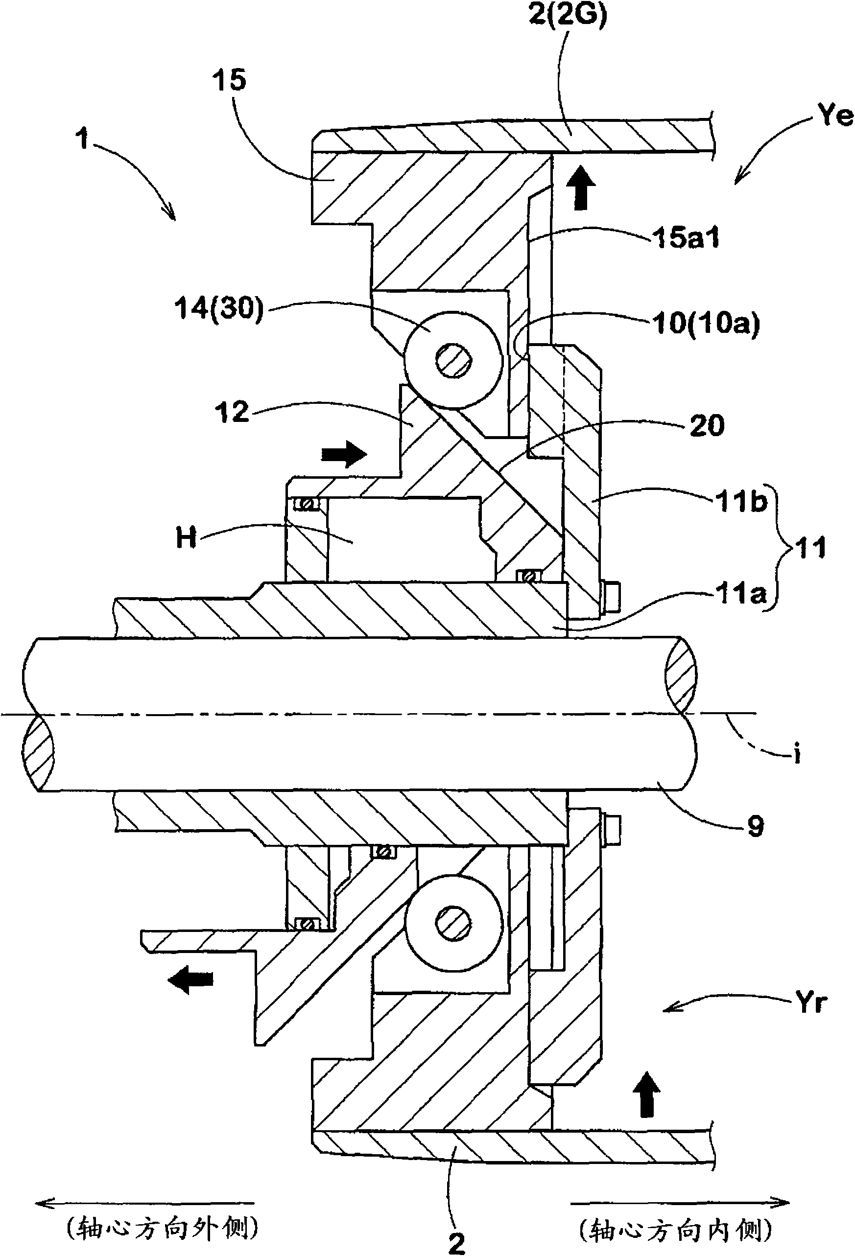
[0035] Next, embodiments of the present invention will be described in detail. figure 1 It is a sectional view showing the axial direction of the main part of the tire building drum of the present invention. Here for the sake of illustration, figure 1 The tire building drum 1 in the diameter-expanded state Ye is shown on the upper side of the axis i of the drum support shaft 9, and the tire building drum 1 in the reduced-diameter state Yr is shown on the lower side.

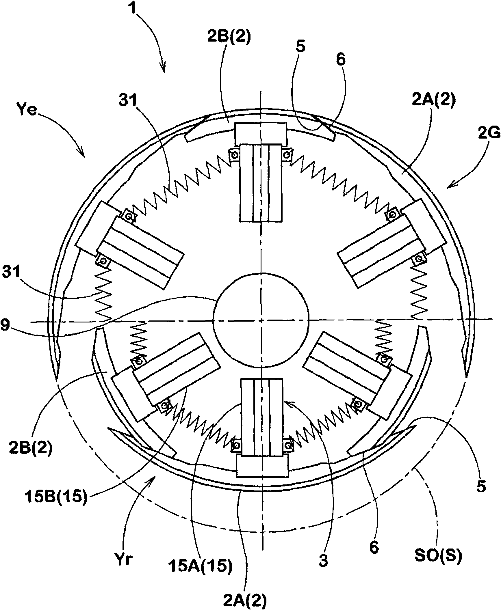
[0036] Such as figure 1 , 2 As shown, the tire building drum 1 of this embodiment has: a combined mold group 2G composed of a plurality of divided molds 2 divided in the circumferential direction, and an expansion and contraction unit 3 for moving each combined mold 2 radially inward and outward. In the expansion / contraction unit 3 , the split mold 2 moves between a diameter-shrinking state Yr in which the outer surface S shrinks in diameter and a diameter-expanding state Ye in which the outer surface S exp...


PUM


Abstract

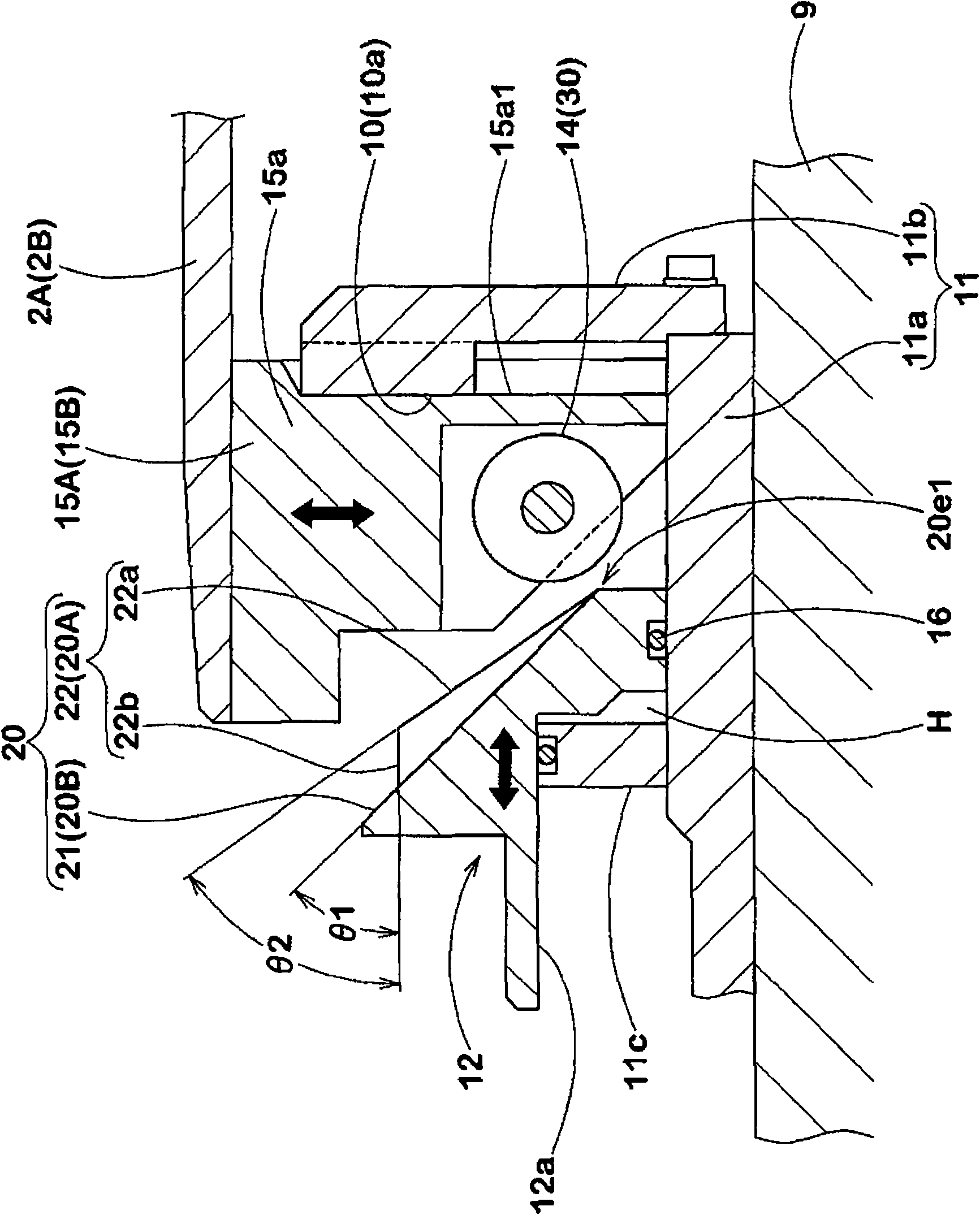
The invention provides a tire assembly drum, capable of suppressing the abrasion between side ends of a combination die. The tire assembly drum comprises a first and a second combination die which are assembled alternately in a circumferential direction and can move between a shrinking state and an expanding state by aid of an expanding unit. The expanding unit comprises a cone-shaped sliding body which is capable of being guided to move in an axis direction and is provided with a guiding face at the inner end in the axis direction, a first and a second moving piece which are capable of being guided to move in and out in a radial direction and are provided with a first and a second combination die at the outer end in the radial direction. The guiding face consists of a first oblique face connected to a first moving piece in a snap-fit, a second oblique face which inclines differently from the first oblique face and is connected to a second moving piece in a snap-fit. At the time of expanding, the first combination die reaches to the expanding position earlier than the second combination die. At the time of shrinking, the first combination die moves from the expanding position towards the inner side in a radial direction later than the second combination die.

Description

technical field [0001] The present invention relates to a tire building drum for forming a tire component by winding a sheet-shaped body for forming a tire on an outer surface. Background technique [0002] In the manufacturing process of a green tire, for example, when forming tire components such as an inner liner rubber and a carcass ply, a sheet-shaped body for forming the above-mentioned tire components is wound in the circumferential direction on the outer surface of a tire building drum. form a cylinder. [0003] In this tire building drum, in order to remove the wound cylindrical tire component, it is necessary to reduce the diameter, so as Figure 7 In the conventional structure shown, the drum part of the tire building drum a is formed by a plurality of split molds b divided in the circumferential direction, and each split mold b can be moved radially inward and outward by using expansion and contraction units (for example, refer to the patent document 1). [000...

Claims


Application Information

Patent Timeline
IPC IPC(8): B29D30/24
Inventor 长治雅伦
Owner SUMITOMO RUBBER IND LTD
Learn More