Annular water-blowing device

An annular and annular groove technology, applied in furnaces, heat treatment equipment, quenching agents, etc., can solve problems such as troubled technicians, inconvenient handling, and unclean water blowing.

Active Publication Date: 2010-12-22
河南恒星钢缆股份有限公司
View PDF6 Cites 2 Cited by
  • Summary
  • Abstract
  • Description
  • Claims
  • Application Information

AI Technical Summary

Problems solved by technology

[0003] Excessive water adhered to the surface of the steel cable after water quenching will bring inconvenience to the subsequent process. Today's steel c

Method used


Image

  • Annular water-blowing device
  • Annular water-blowing device
  • Annular water-blowing device

Examples


Embodiment 1

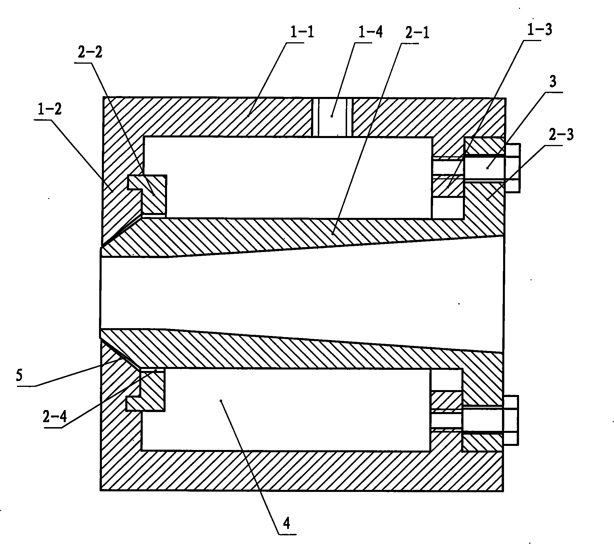
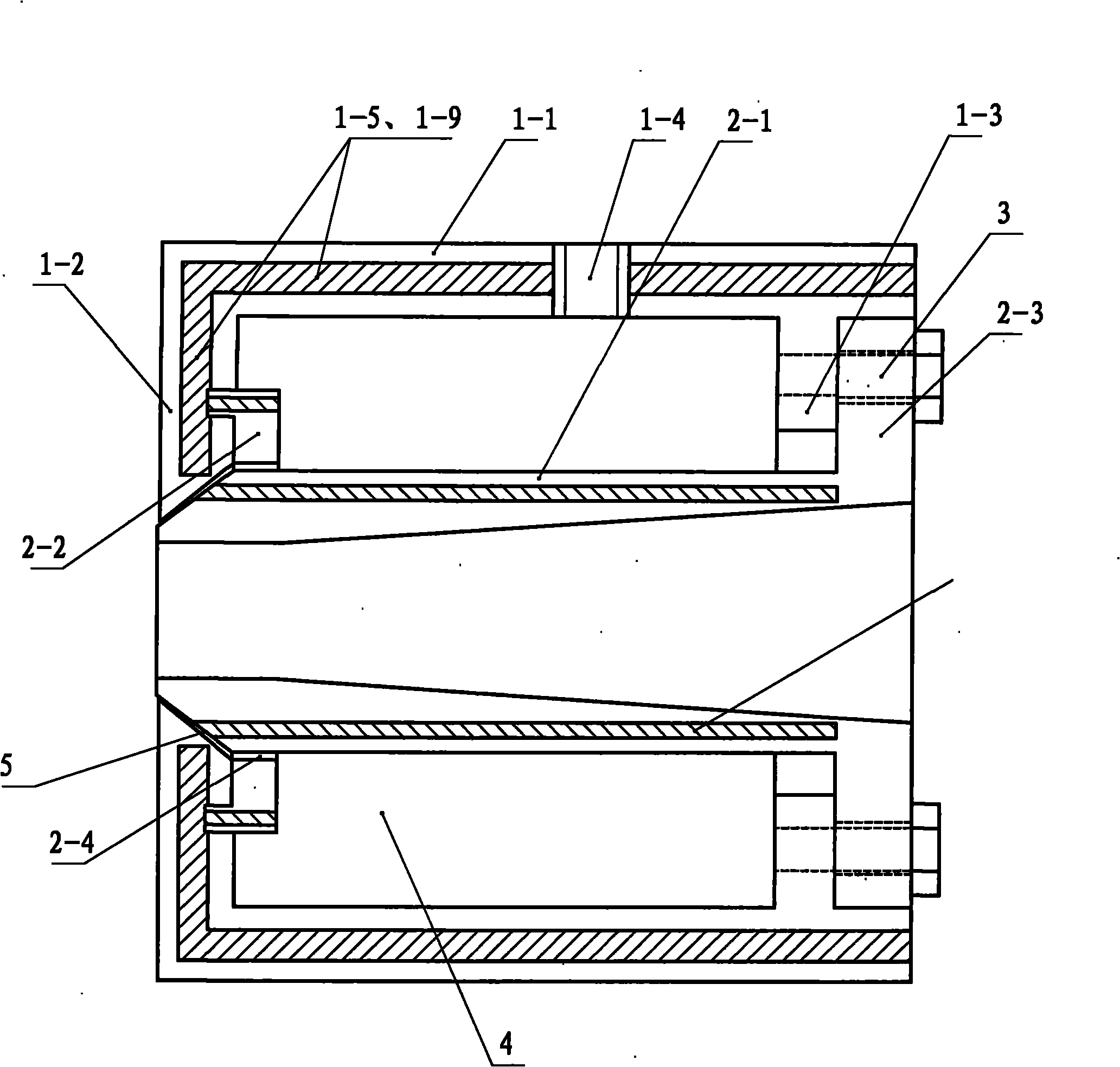
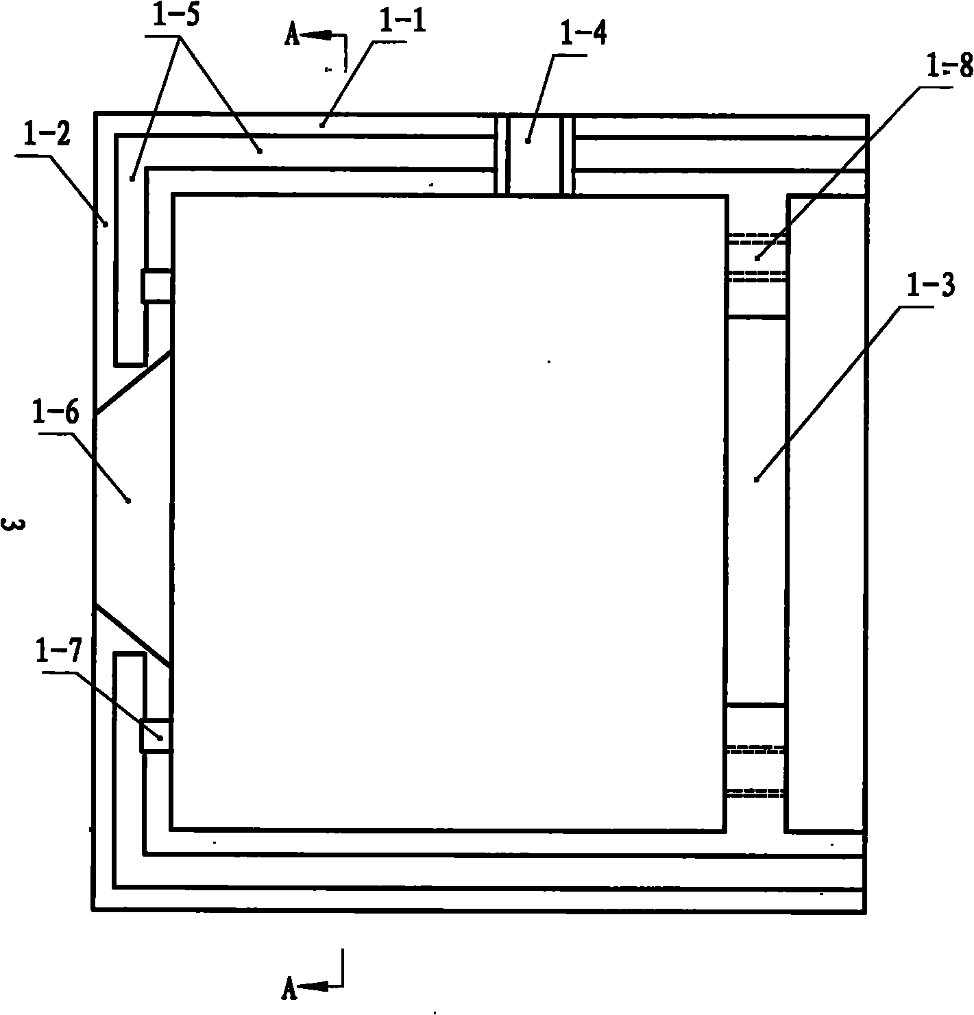
[0035] Embodiment one: see Figure 1-Figure 14 , a ring-shaped water blowing device in the figure, which contains a hollow inner sleeve and a hollow outer sleeve. The two ends of the inner tube body of the outer sleeve are respectively provided with a connecting plate and a positioning plate, and the outer two ends of the tube body of the inner sleeve There are matching connecting discs and positioning discs at the end, and the connecting discs of the outer sleeve and the inner sleeve are connected together by fasteners. There are bolt holes on the connecting discs of the outer sleeve and the inner sleeve, and the positioning discs of the outer sleeve and the inner sleeve are connected together. A matching positioning structure is provided between them; an annular air chamber is formed inside the outer sleeve body and the inner sleeve body; the side wall of the outer sleeve is provided with an air inlet to communicate with the air chamber; the middle part of the positioning pla...

Embodiment 2

[0044] Embodiment two: see Figure 15 , the second embodiment is basically the same as the first embodiment, and the similarities will not be repeated. The difference is that the annular groove on the inner surface of the positioning plate of the outer jacket in the second embodiment is a trapezoidal groove with an outer width and an inner narrowness. The annular convex edge of the outer surface of the positioning plate of the inner sleeve is a trapezoidal convex edge matching the above-mentioned trapezoidal groove, and the positioning plate and the connecting plate of the inner sleeve are respectively press-fitted on the positioning plate and the connecting plate of the outer sleeve in the same direction. plate.


PUM


Abstract

The invention provides an annular water-blowing device, comprising a hollow inner housing and a hollow external housing, wherein the two ends inside the tube body of the external housing are respectively provided with a terminal pad and a locating disc; the two external ends of the tube body of the inner housing are respectively provided with a matching terminal pad and a matching locating disc; the terminal pads of the external housing and the inner housing are connected by a fastener and location structures are arranged between the locating discs of the external housing and the inner housing and are matched mutually; an annular air chamber is formed inside the external housing tube and outside the inner housing tube; the side wall of the external housing is provided with an air inlet which is communicated with the air chamber; and the middle part of the locating disc of the external housing is provided with a conical bore, the part of the front end of the inner housing, which extends out of the locating disc, is a conical head which is homocentric with the conical bore, a certain distance exists between the surface of the conical bore and the surface of the conical head so as to form a conical annular air outlet gap, and the locating disc of the inner housing is provided with a certain amount of air holes which are communicated with the air chamber and the air outlet gap. The device has artful structure and strong water-blowing dynamics and can blow-dry the water on the surface of a wire rope.

Description

1. Technical field [0001] The invention relates to the removal of cooling water in the production process of steel cables, in particular to an annular water blowing device. 2. Background technology [0002] Heat treatment heat treatment is an inevitable process in the production process of steel cables. The water quenching process involved refers to the process of rapidly cooling the heated steel cable in water to improve the internal structure of the steel cable and wire, and improve the quality of the steel cable. performance of the cable. [0003] Too much water adhering to the surface of the steel cable after water quenching brings inconvenience to the subsequent processing. Today's steel cable manufacturers use water blowing devices to generally have the problem of unclean water blowing, which has always troubled the majority of technicians. 3. Contents of the invention [0004] In order to solve the above problems, the present invention proposes an annular water blo...

Claims


Application Information

Patent Timeline
IPC IPC(8): C21D9/00C21D1/60
Inventor 谢保万焦德库
Owner 河南恒星钢缆股份有限公司
Why Eureka
Try Eureka