
Three-jaw chuck

A three-jaw chuck and clamping structure technology, applied in the field of mechanical processing, can solve the problems of low pressure of deformation pressing screw and rear platen, cumbersome clamping adjustment, uneven force, etc. Reliable and even force

Inactive Publication Date: 2010-12-29
溧阳市虹翔机械制造有限公司
View PDF0 Cites 9 Cited by
  • Summary
  • Abstract
  • Description
  • Claims
  • Application Information

AI Technical Summary

Problems solved by technology

However, because of the uneven force applied to the four screw compression points after adjusting the shape, the hole deformation after processing is relatively large
In addition, due to the cumbersome adjustment of the clamping and the fear of deformation, the compression screw and the lower pressure of the rear platen will affect the speed of processing and the depth of the knife and the amount of cutting. The shift output is only about 28 pieces

Method used


Image

  • Three-jaw chuck
  • Three-jaw chuck
  • Three-jaw chuck

Examples


Embodiment Construction

[0013] The present invention will be further described below in conjunction with the accompanying drawings and specific embodiments.

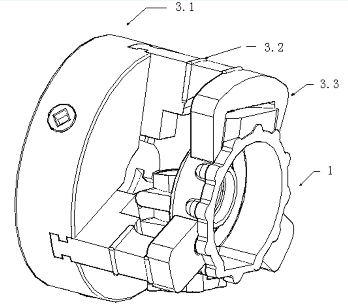
[0014] A three-jaw chuck, comprising a three-jaw chuck body 3.1, on which three bevel teeth 3.2 of the three-jaw chuck body 3.1 are respectively provided with locking structures 3.3; The structure 3.3 corresponds to the shape of the corresponding part of the processed workpiece. After the processed workpiece is clamped in the clamping structure 3.3, the axis of the processed workpiece corresponds to the axis of the three-jaw chuck body 3.1.

[0015] The connection between the clamping structure 3.3 and each bevel tooth 3.2 is a fixed connection or a detachable connection.

[0016] The fixed connection between the locking structure 3.3 and the respective bevel teeth 3.2 is realized by welding.

[0017] The realization structure of the detachable connection between the locking structure 3.3 and the respective bevel tooth 3.2 is that a correspond...


PUM


Abstract

The invention relates to a three-jaw chuck, which comprises a three-jaw chuck body. Three bevel gears of the three-jaw chuck body are respectively provided with clamping structures; the shape of the clamping structures which are respectively arranged on the three bevel gears corresponds to that of corresponding parts of a machined workpiece; after the machined workpiece is clamped in the clamping structure, the axis of the machined workpiece corresponds to that of the three-jaw chuck body. After the three-jaw chuck is adopted, repeated positioning performance is high and a clamping point is uniformly stressed in the process of machining the workpiece, so the problem of hole deformation is effectively solved; and the three jaws are convenient and firm to clamp and output per shift is improved to about 70 workpieces. In addition, different clamping structures are replaced for different workpieces by using the standard three-jaw chuck body.

Description

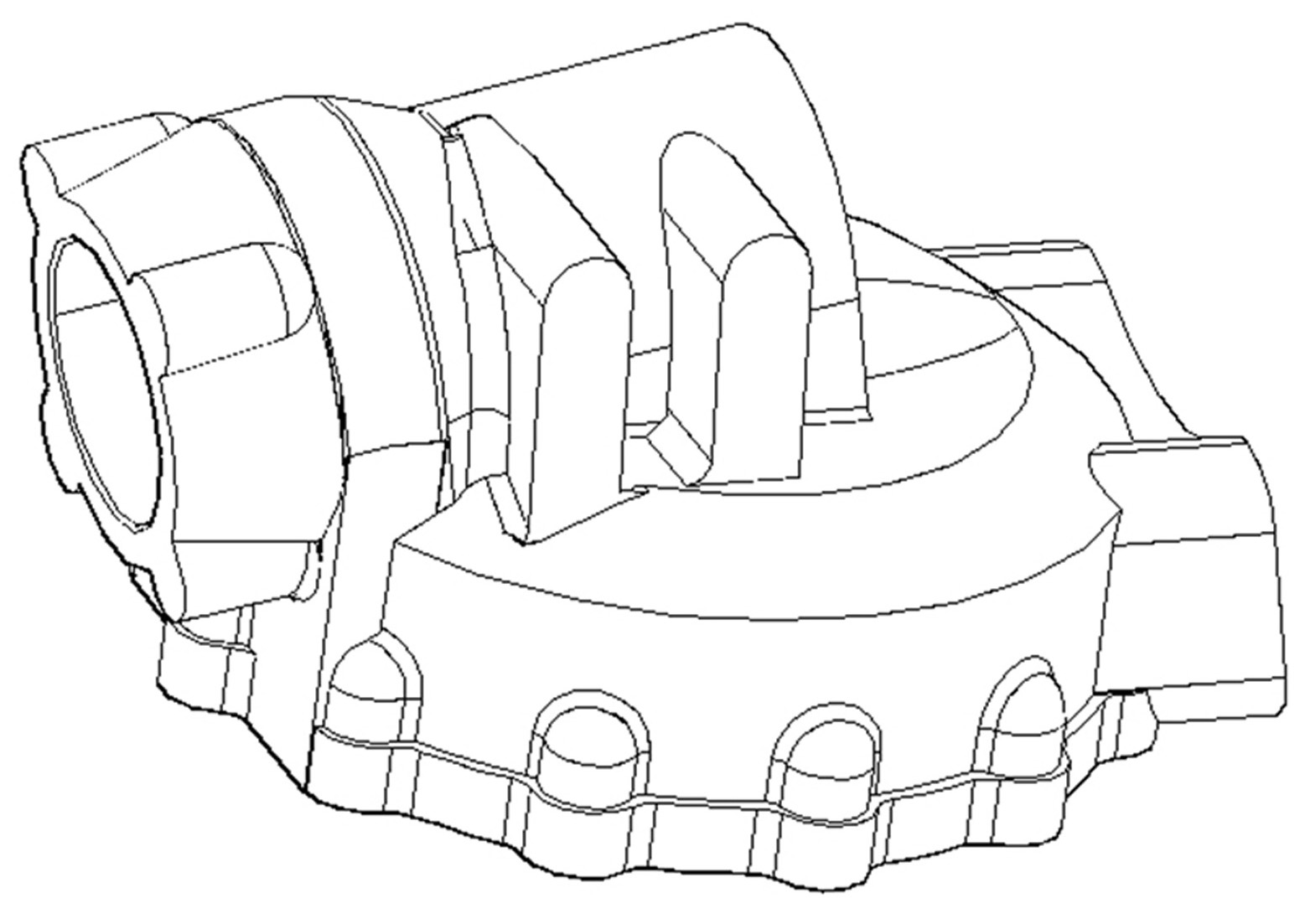
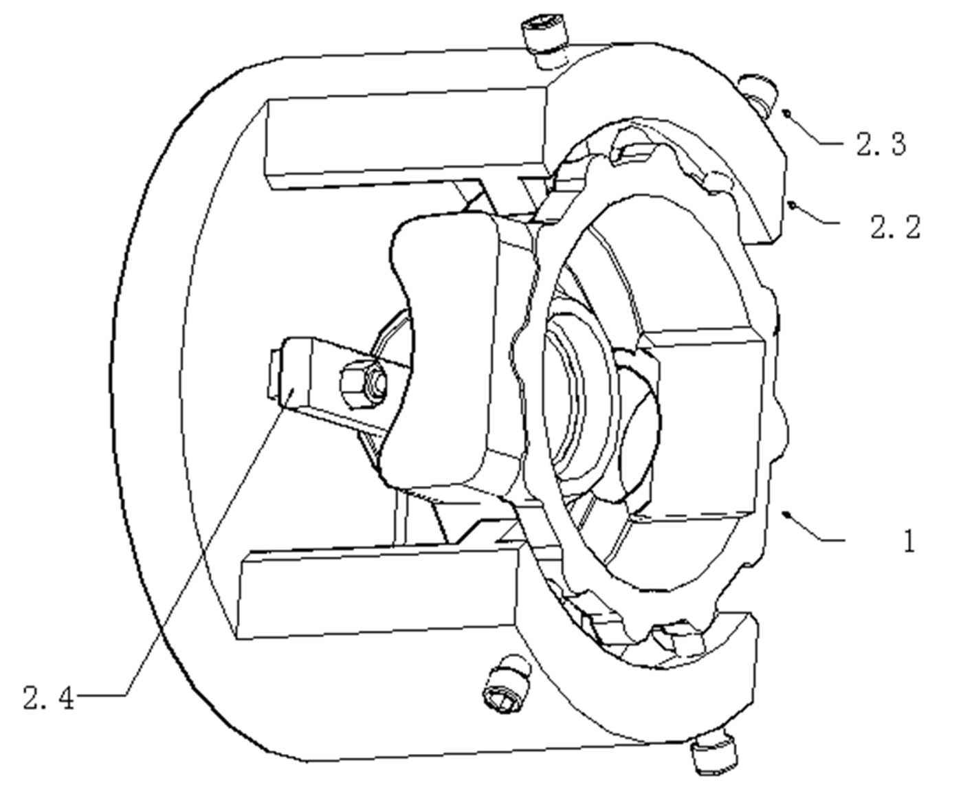
technical field [0001] The invention belongs to the technical field of mechanical processing, in particular to a three-jaw chuck for processing special-shaped workpieces. Background technique [0002] In the prior art, some workpieces with irregular shapes (such as figure 1 Housing in the middle), it is difficult to clamp with standard three-jaw and four-jaw tooling. To solve this problem, there are also some tooling, such as figure 2 In the semi-sleeve-shaped tooling shown, the workpiece 1 is positioned on the plane by the inner step of the tooling main body 2.2, and the shape of the workpiece is adjusted and compressed with the screw rod 2.3, and then the rear pressing plate 2.4 is locked. However, due to the uneven force on the four screw compression points after adjusting the shape, the hole deformation after processing is relatively large. In addition to the cumbersome adjustment of the clamping, the fear of deformation and the small pressure of the compression scre...

Claims


Application Information

Patent Timeline
IPC IPC(8): B23B31/10
Inventor 吕燕翔吕伟龙史仁龙万传友彭芳美周国忠
Owner 溧阳市虹翔机械制造有限公司
Learn More