
Eureka
For R&D, Eureka makes reading and utilizing patents & technical documents easy.
Eureka AIR
Designed for self-driven R&D workflows. Generate viable solutions, solve complex R&D challenges, empower your innovation with AI.

Eureka Materials
Designed for material experts only. Revolutionize your material R&D, from search, analyze, to developing new materials.

TechResearch
Generate reliable direction feasibility study reports for your R&D in just a few steps.

TechSeek
Discover and master advanced knowledge NOW. Basics, ideas, possibilities, all at once.

TechMind
As an expert in R&D Theories, TechMind can generates customized viable solutions instantly.

TechRisk
Analyze your overall solution with one click, know your potential R&D risks in advance.

TechMonitor
Get weekly tech updates, stay abreast of the latest tech innovations and key insights.
Press
A technology of presses and bars, applied in the field of presses, can solve the problems of complex structure, large action space, increase in quantity, etc., and achieve the effect of structure simplification
- Summary
- Abstract
- Description
- Claims
- Application Information
AI Technical Summary
Problems solved by technology
Method used
Image

Examples
Embodiment Construction
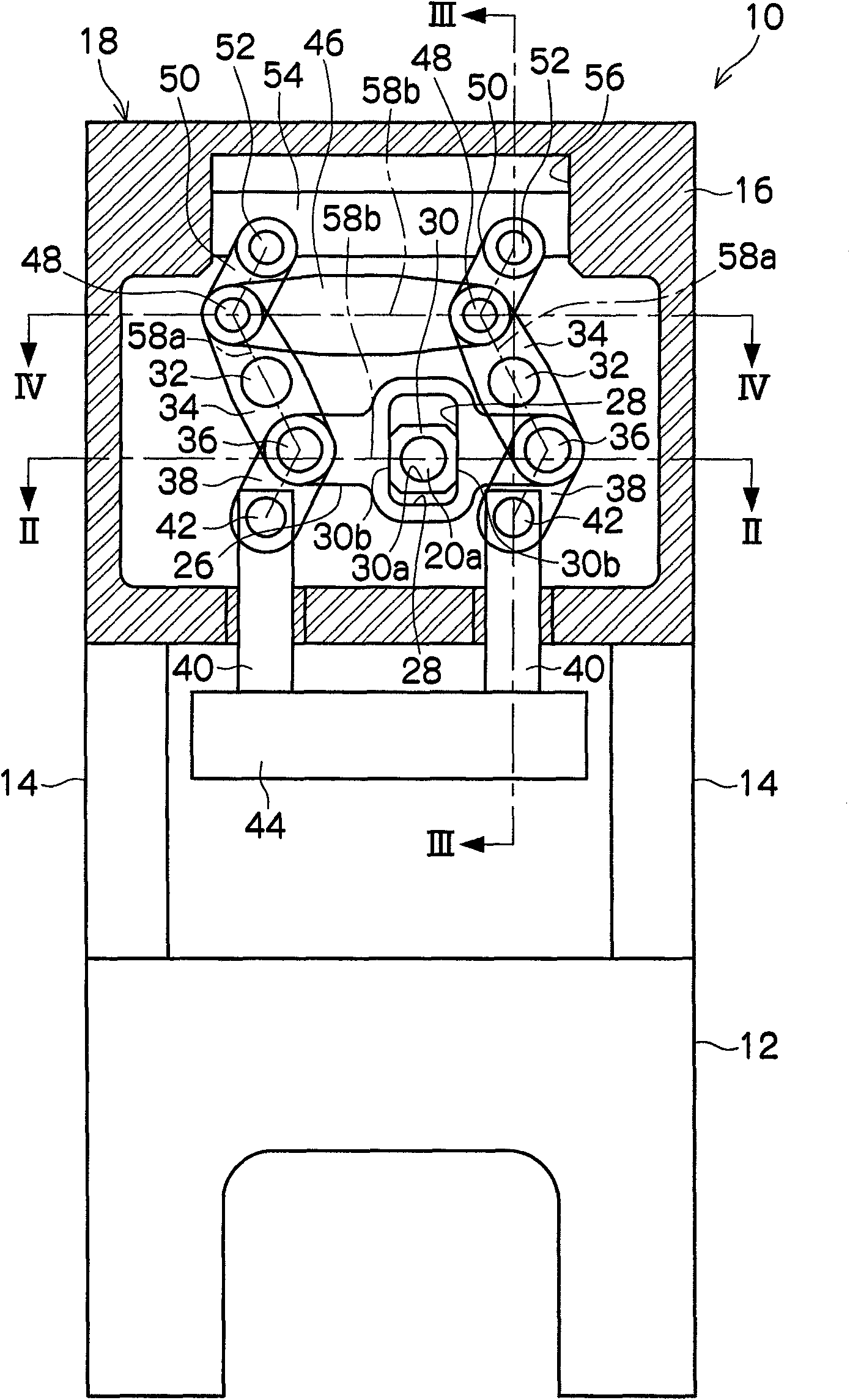
[0025] Such as figure 1 As shown, the press 10 of the present invention includes a machine base 12 and a frame 18, wherein the frame 18 has a plurality of struts 14 upstanding from the machine base to hold on the machine base in a spaced manner from the machine base 12. The upper beam (crown) 16 . The beam 16 is formed in a rectangular box shape as a whole, and a lower mold part is provided on the base 12 located below the beam 16, although not shown in the figure.
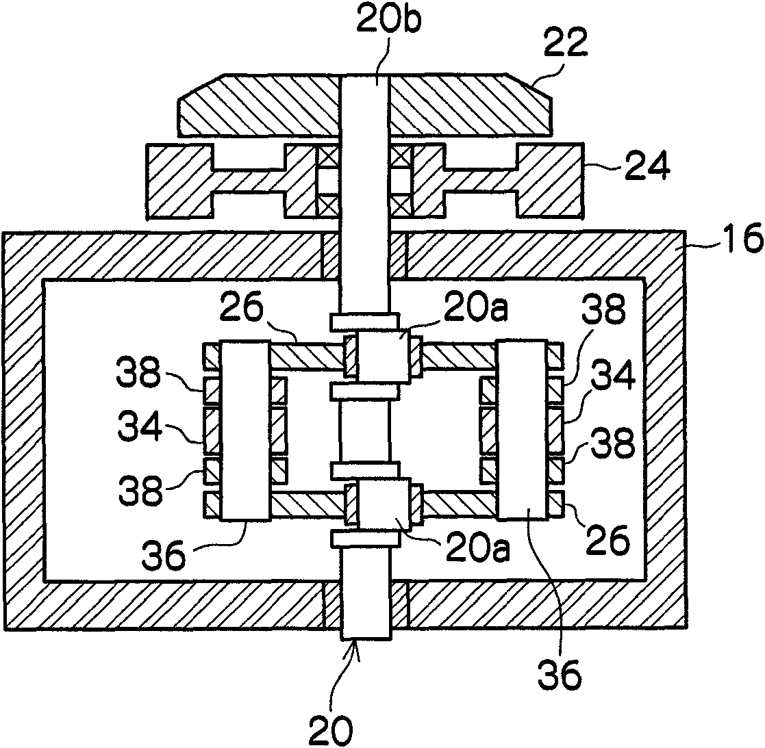
[0026] Such as figure 2 As shown, in the beam 16 , a crankshaft 20 having a pair of eccentric portions 20 a has one end of a main shaft portion 20 b protruding greatly from the beam 16 , and the crankshaft 20 is rotatably held. The protruding end of the main shaft part 20b is provided with: a driving force transmission device 22 having a conventionally known clutch and brake capable of intermittently transmitting the rotational force surrounding the main shaft part 20b of the crankshaft 20; and a flywheel 24. ...
PUM
 Abstract
Description
Claims
Application Information
 - R&D Engineer
- R&D Manager
- IP Professional
- Industry Leading Data Capabilities
- Powerful AI technology
- Patent DNA Extraction
Browse by: Latest US Patents, China's latest patents, Technical Efficacy Thesaurus, Application Domain, Technology Topic, Popular Technical Reports.
© 2024 PatSnap. All rights reserved.Legal|Privacy policy|Modern Slavery Act Transparency Statement|Sitemap|About US| Contact US: help@patsnap.com