Guide rod type diesel pile hammer with vertical landing gear

A technology of landing gear and piling hammer, which is applied in the direction of sheet pile walls, buildings, and foundation structure engineering, and can solve problems such as deformation and damage of piling frames, external force wire rope breakage, and high labor intensity.

A technology of landing gear and piling hammer, which is applied in the direction of sheet pile walls, buildings, and foundation structure engineering, and can solve problems such as deformation and damage of piling frames, external force wire rope breakage, and high labor intensity.

CN101929156BActive Publication Date: 2012-11-28JIANGSU JUWEI MACHINERY

Image

  • Guide rod type diesel pile hammer with vertical landing gear
  • Guide rod type diesel pile hammer with vertical landing gear
  • Guide rod type diesel pile hammer with vertical landing gear

Examples


Embodiment Construction

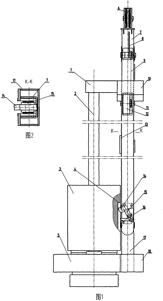
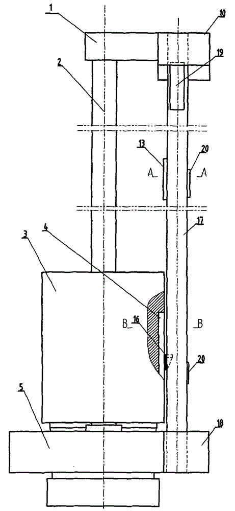
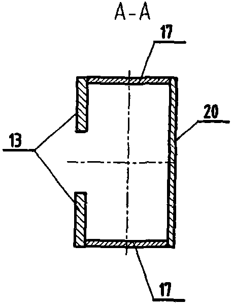
[0019] exist figure 1 , figure 2 In the shown guide rod diesel piling hammer with vertical landing gear, the piling hammer includes a top beam 1, a guide rod 2, a cylinder hammer 3 and a piston 5, and two guide rods 2 are arranged parallel to each other. The top beam 1 is fixedly installed on the upper ends of the two guide rods 2, the lower end of the guide rod 4 is fixedly installed on the piston 5, and a pile cap is installed on the bottom surface of the piston 5, and the cylinder hammer 3 is located between the top beam 1 and the piston 5, And the cylinder hammer 3 can slide and bounce up and down along the two guide rods 2, and an upper guide claw 10 and a lower guide claw 18 are respectively fixedly arranged on the same outer side of the top beam 1 and the piston 5. Different from the prior art, the undercarriage 7 is vertically arranged on the outside of the piling hammer cylinder hammer 3, and the position is on the same side as the upper guide claw 10 and the lower ...


PUM


Abstract

The invention discloses a guide rod type diesel pile hammer with a vertical landing gear, which comprises a top transverse beam, a guide rod, a cylinder hammer and a piston, wherein the top transverse beam and the piston are respectively installed on the upper and the lower ends of the guide rod; the cylinder hammer can slide upwards and downwards along the guide rod; a landing gear is verticallyarranged outside the cylinder hammer, and is provided with a lifting hook and a hammer lifting hook; the hammer lifting hook corresponds to a cylinder hammer hook groove on the cylinder hammer, and is connected with a link mechanism of the hammer lifting hook; and a decoupling stop block and a hammer hooking stop block are fixedly connected between the top transverse beam and the piston. The pilehammer has the advantages of completely preventing the landing gear from colliding with the cylinder hammer and the top transverse beam in a work process, automatically hooking and decoupling the landing gear and facilitating the operation.

Description

technical field [0001] The invention relates to equipment for building foundation construction, more specifically, to a landing gear of a guide rod type diesel piling hammer. Background technique [0002] Guide rod type diesel piling hammer (hereinafter referred to as piling hammer) is a kind of piling equipment for construction foundation engineering. It is widely used because of its advantages such as large impact force, high work efficiency, strong reliability, and convenient use and maintenance. Existing piling hammers are all composed of top beam, landing gear, cylinder hammer, piston, guide rod and oil circuit system. The top beam and piston are respectively fixed on the upper and lower ends of the guide rod. Between the top beam and the piston, it moves up and down guided by the guide rod, and the landing gear is above the cylinder hammer. [0003] When the piling hammer is started, the landing gear falls along the guide rod and collides with the upper plane of the c...

Claims


Application Information

Patent Timeline
28 Nov 2012
Publication
CN101929156B
IPC
E02D7/12; E02D7/14; E02D7/16
Inventors
余有存; 许向华