Pile driver for construction site

A technology for construction sites and pile drivers, which is used in construction, sheet pile walls, infrastructure engineering, etc., can solve the problems of poor straightness of pile drivers, inclined driving of wooden piles into the ground, and low efficiency of wire rope lifting, and achieves up and down reciprocating motion. The effect of smoothness, increasing service life and improving piling efficiency

Inactive Publication Date: 2020-12-11
JIANGSU PROVINCIAL CONSTR GRP CO LTD +1
View PDF4 Cites 6 Cited by
  • Summary
  • Abstract
  • Description
  • Claims
  • Application Information

AI Technical Summary

Problems solved by technology

[0003] When the existing pile driver strikes the wooden pile progressively, the pile hammer is generally driven up by the steel wire rope, and then the pile driver is driven down by the weight of the pile hammer to drive the pile. And the steel wire rope has low lifting efficiency, which leads to the defect of low piling efficiency of the pile driver

Method used


Image

  • Pile driver for construction site
  • Pile driver for construction site
  • Pile driver for construction site

Examples


Embodiment 1

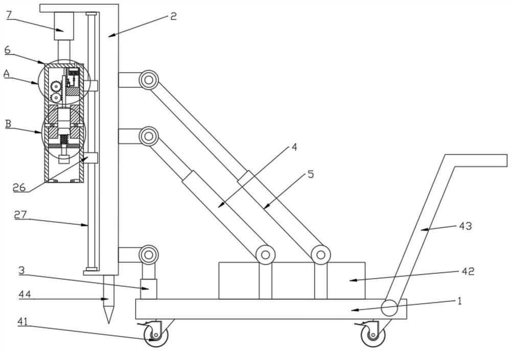
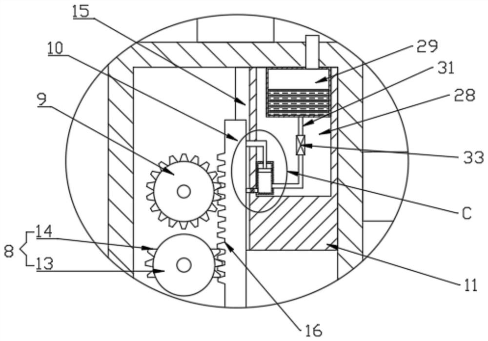
[0026] see Figure 1-3 , a pile driver for a construction site, a pile driver for a construction site, comprising a base plate 1, a bracket 2 and a piling mechanism, the top surface of the base plate 1 passes through an electric hydraulic cylinder one 3, an electric hydraulic cylinder two 4 and an electric hydraulic cylinder The third 5 is connected to the bottom surface of the support 2, the output ends of the electric hydraulic cylinder one 3, the electric hydraulic cylinder two 4 and the electric hydraulic cylinder three 5 are all hinged with the bottom surface of the support 2, and the electric hydraulic cylinder two 4 and the electric hydraulic cylinder three 5 are inclined Set, described piling mechanism comprises piling cylinder 6, driving mechanism and clamping mechanism, and described piling cylinder 6 is connected with support 2 top by electro-hydraulic cylinder 47, and described driving mechanism comprises first gear 8, second gear 9, The guide rod 10 and the slidin...

Embodiment 2

[0033] This embodiment has been improved on the basis of Embodiment 1, specifically:

[0034] A cavity 28 is provided in the sliding box 11, and a lubricating mechanism is provided in the cavity 28. The lubricating mechanism includes an oil storage tank 29 and an oil outlet cylinder 30, and the oil storage tank 29 is fixed on the top of the cavity 28. , and the oil storage tank 29 communicates with the outside of the piling barrel 6 through the infusion tube, the oil outlet barrel 30 is fixed on the side of the cavity 28, and the bottom of the left side of the oil outlet barrel 30 is connected to the bottom of the oil storage tank 29 through the first connecting pipe 31 The bottom of the right side of the oil outlet cylinder 30 communicates with the chute 15 through the second connecting pipe 32, and the first connecting pipe 31 is equipped with a first one-way passage 33 that only allows lubricating oil to flow to the oil outlet cylinder 30 , the second connecting pipe 32 is ...


PUM


Abstract

The invention discloses a pile driver for a construction site. The pile driver comprises a bottom plate, a support and a pile driving mechanism, wherein the pile driving mechanism comprises a pile driving barrel, a driving mechanism and a clamping mechanism; the driving mechanism comprises a first gear, a second gear, a guide rod and a sliding box; and a lubricating mechanism is arranged in the sliding box. By arranging the driving mechanism, compared with a traditional pile driver which pulls a pile hammer through a steel wire rope for striking, the pile driver can drive the pile hammer to repeatedly and rapidly hammer timber piles through a motor, and the pile driving efficiency is greatly improved; and by arranging the lubricating mechanism, the lubricating mechanism is driven to discharge oil while the driving mechanism operates, thus, the driving mechanism operates more smoothly, and equipment is prevented from being disassembled and lubricated.

Description

technical field [0001] The invention relates to the technical field of construction site equipment, in particular to a pile driver for a construction site. Background technique [0002] The pile driver is composed of pile hammer, pile frame and auxiliary equipment. The pile hammer is attached between two parallel vertical guide rods (commonly known as gantry) at the front of the pile frame, and is hoisted with a lifting hook. The pile frame is a steel structure tower frame, and a hoist is provided at the rear of it for lifting piles and pile hammers. There is a guide frame composed of two guide rods in front of the pile frame, which is used to control the direction of pile driving, so that the pile can accurately penetrate into the ground according to the design orientation, and wooden pile support is widely used in water conservancy, bridges, and shallow foundation pits of buildings. When driving wooden piles, it is advisable to drive the wooden piles one by one to a stab...

Claims


Application Information

Patent Timeline
Patent Type & Authority Applications(China)
IPC IPC(8): E02D7/10
CPCE02D7/10
Inventor 李逵吴继坤陈思宁祝捷陈禹良储志锋顾浩计佳戴萍王丽丽
Owner JIANGSU PROVINCIAL CONSTR GRP CO LTD
Why Eureka
Try Eureka