
Stable hydraulic pie driving equipment for buildings

A kind of piling equipment and construction technology, applied in construction, sheet pile wall, foundation structure engineering, etc., can solve the problems of repeated piling operation, difficulty, etc., and achieve the effect of improving efficiency and reducing the probability of damage

Inactive Publication Date: 2018-03-06
陈佳敏
View PDF2 Cites 5 Cited by
  • Summary
  • Abstract
  • Description
  • Claims
  • Application Information

AI Technical Summary

Problems solved by technology

[0009] In order to solve the above-mentioned technical problems, the present invention provides stable hydraulic piling equipment for construction to solve the problem that the existing hydraulic piling machine hammer mechanism is not easy to cause piles to be driven into the foundation when the pile encounters a hard foundation.

Method used


Image

  • Stable hydraulic pie driving equipment for buildings
  • Stable hydraulic pie driving equipment for buildings
  • Stable hydraulic pie driving equipment for buildings

Examples


Embodiment

[0033] as attached figure 1 to attach Figure 8 Shown:

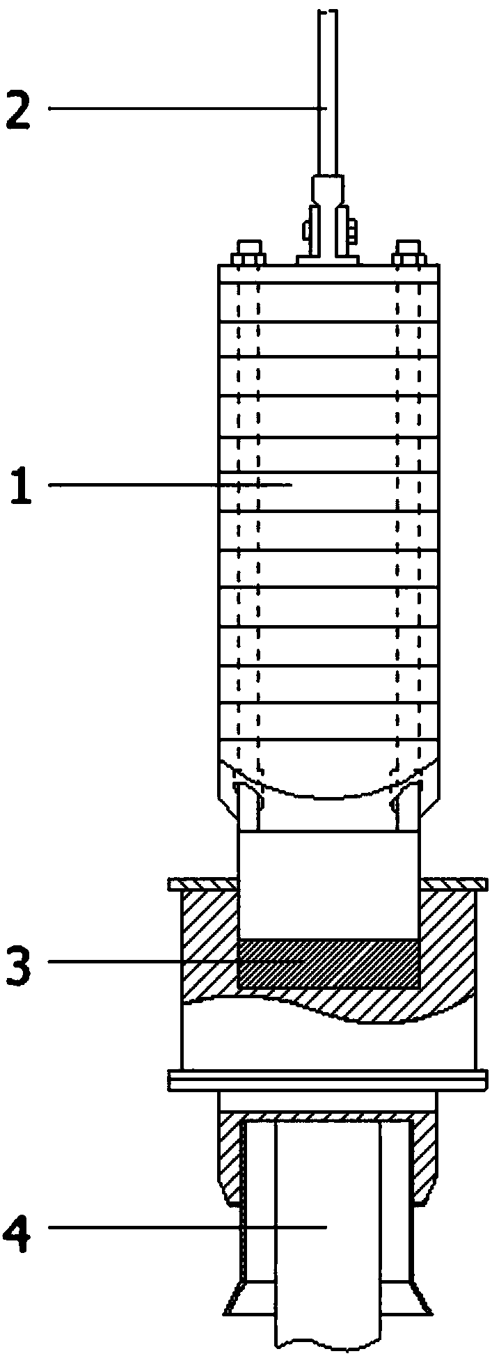
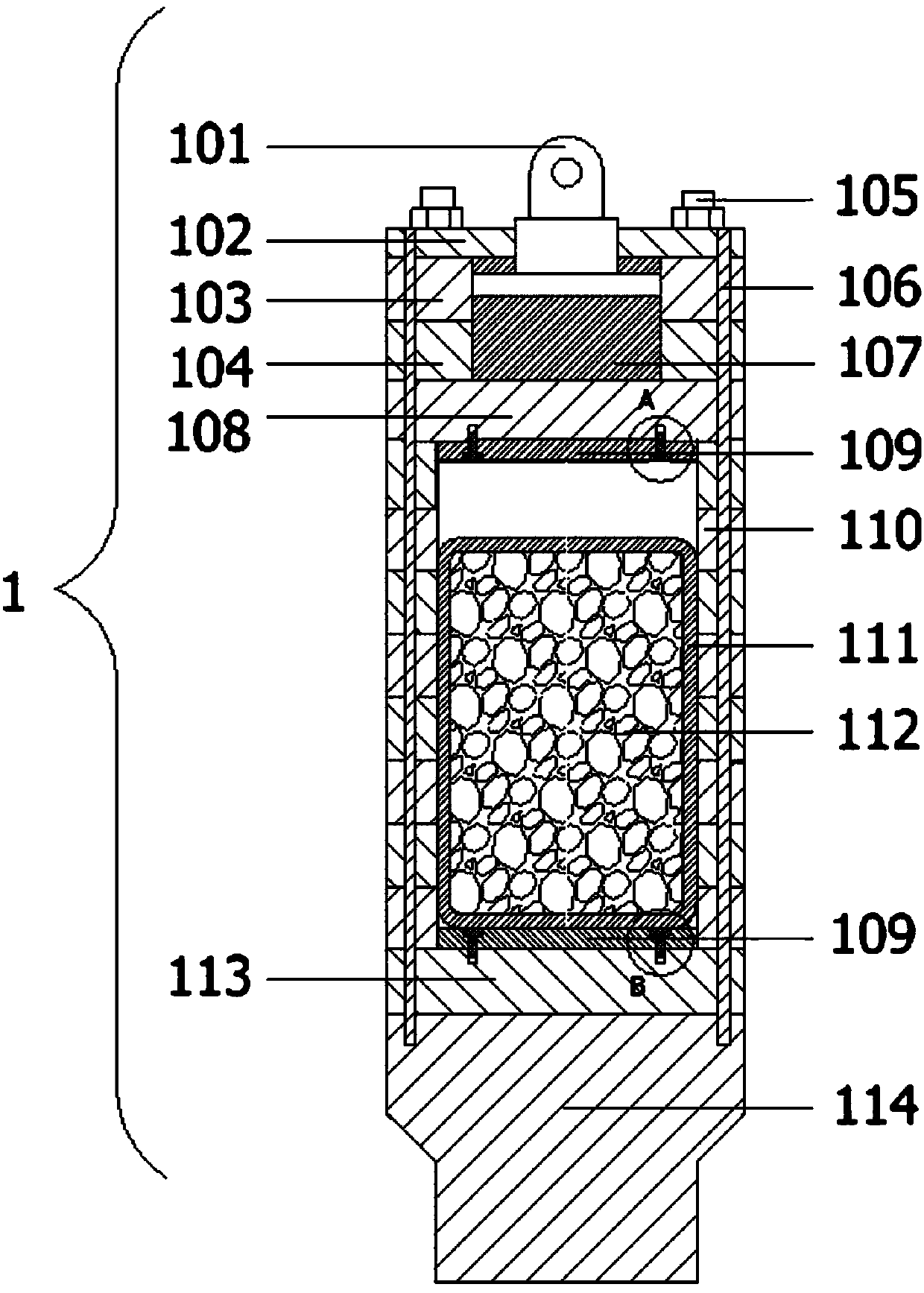
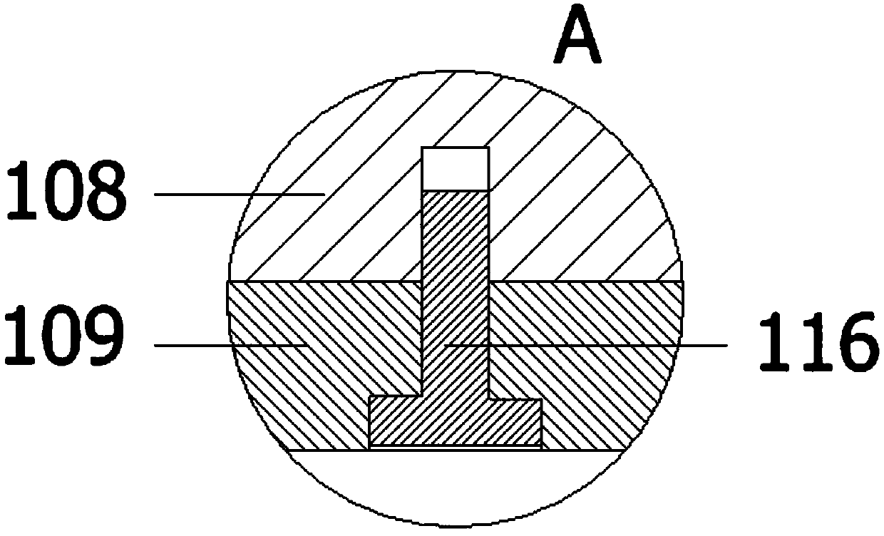
[0034]The present invention provides stable hydraulic piling equipment for construction, comprising hydraulic pile driver hammer head mechanism 1, cylinder piston rod 2, hammer pad 3, pile 4, oil cylinder connection seat 101, fixed pressure plate 102, upper ring block 103, lower ring block 104, Bolt 105, fixed bolt 106, buffer pad 107, upper pressing plate 108, buffering protection pad 109, ring pressure block 110, steel wire mesh cover 111, metal particle filler 112, lower pressing plate 113, impact head 114, lock nut 115 and fixing Bolt 116; the top of the hammer head mechanism 1 of the hydraulic pile driver is fixedly connected with the cylinder piston rod 2, and the bottom of the hammer head mechanism 1 of the hydraulic pile driver contacts the hammer pad 3, and the pile 4 is below the hammer pad 3; the hydraulic pile driver The hammer head mechanism 1 is composed of an oil cylinder connecting seat 101, a fixed pre...


PUM


Abstract

The invention provides stable hydraulic pile driving equipment for buildings. The stable hydraulic pile driving equipment comprises a hydraulic pile driver hammer mechanism and fixing bolts, wherein an oil cylinder piston rod is fixedly connected to the top of the hydraulic pile driver hammer mechanism, the bottom of the hydraulic pile driver hammer mechanism is in contact with a hammer pad, and apile is arranged under the hammer pad; a buffering protection pad with the same diameter as the inner rings of annular pressure blocks is fixedly mounted at the axis of the bottom of an upper pressing plate through two fixing bolts; and a buffering protection pad with the same diameter as the inner rings of the annular pressure blocks is fixedly mounted at the axis of the top of a lower pressingplate through two fixing bolts. The number of the annular pressure blocks is but not limited to eight groups and can be adjusted through increase / reduction. The height of a hollow cavity is changed bychanging the number of the annular pressure blocks, so that a steel wire mesh sleeve is temporarily separated from the bottom end surface of the hollow cavity when a hitting head descends to hit, andthen the top end surface of the hollow cavity exerts a stronger hitting force onto the steel wire mesh sleeve to facilitate improvement of the pile driving efficiency.

Description

technical field [0001] The invention belongs to the technical field of pile machinery, in particular to stable hydraulic pile driving equipment for construction. Background technique [0002] The hydraulic piling hammer is a new type of engineering machinery developed to overcome the noise and pollution of the diesel hammer. It is widely used in the construction of pile foundations in bridges, industries, and buildings. In the pile hammer hammering system, the hammer head reciprocates up and down, strikes the hammer pad, and transmits the impact force to the pile. [0003] In the prior art, the head of the hydraulic piling hammer is a whole piece of forged steel processed into a cylindrical or cuboid shape. Since the work of the piling hammer mainly utilizes the gravitational potential energy of the hammer head, the weight of the hammer head is relatively large. The processing of the whole hammer head has special requirements on the bearing capacity of the machine tool, and...

Claims


Application Information

Patent Timeline
Patent Type & Authority Applications(China)
IPC IPC(8): E02D7/08E02D7/14E02D13/10
CPCE02D7/08E02D7/14E02D13/10
Inventor 陈佳敏倪翔李浩
Owner 陈佳敏
Learn More