Device for separating lead frame from flow channel

A separation device and lead frame technology, applied in electrical components, semiconductor/solid-state device manufacturing, circuits, etc., can solve the problems of insecurity, low product qualification rate, low efficiency, etc., and achieve the effect of improving safety and improving separation efficiency.

Inactive Publication Date: 2010-12-29
TONGLING JIANXI PRECISION PARTS
View PDF3 Cites 4 Cited by
  • Summary
  • Abstract
  • Description
  • Claims
  • Application Information

AI Technical Summary

Problems solved by technology

[0003] The purpose of the present invention is to solve the problems of unsafe, low efficiency an

Method used


Image

  • Device for separating lead frame from flow channel
  • Device for separating lead frame from flow channel
  • Device for separating lead frame from flow channel

Examples


Embodiment Construction

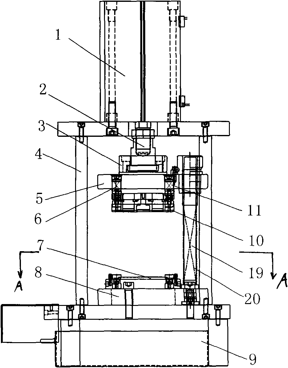
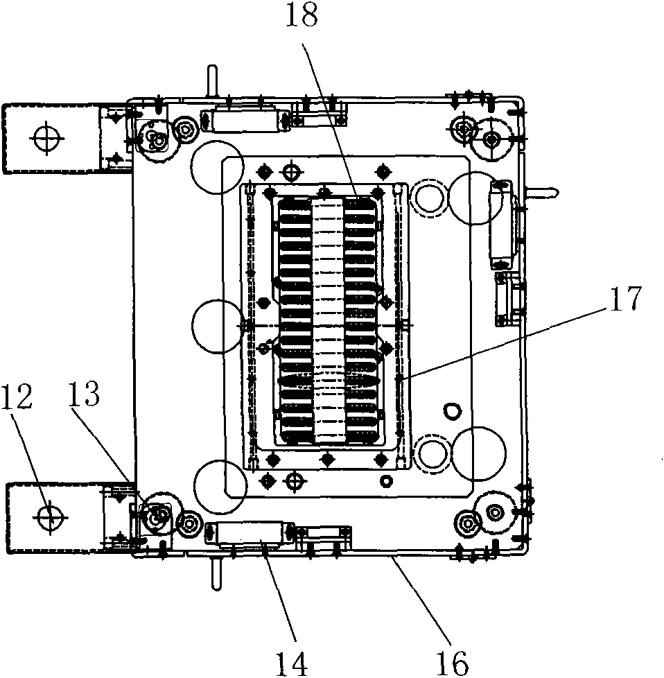
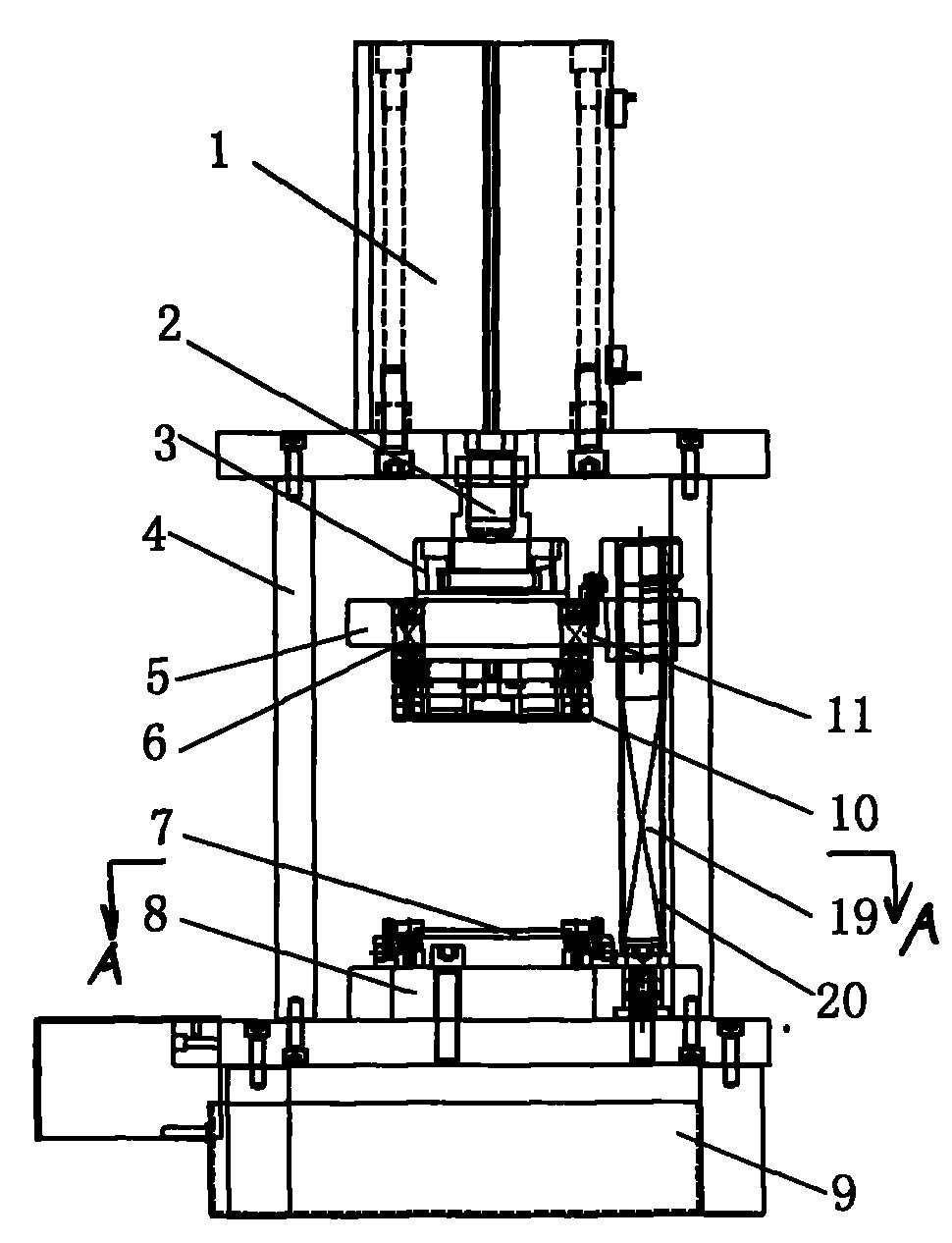
[0013] The lead frame and flow channel separation device of the present invention, such as figure 1 As shown, it includes a closed frame-shaped frame 4, a separating mold used to separate the lead frame 18 from the runner, and a cylinder 1 to provide power. The frame 4 is provided with movable doors 16 on both sides. In order to make the movable door 16 closed, it can not be easily opened such as figure 2 As shown, a magnetic bump 14 is provided under the frame 4, and when the movable door 16 is closed, the magnetic bump 14 is attracted.

[0014] The separating mold is composed of a movable mold and a fixed mold adapted to it. The movable mold includes a mounting plate 5 and a punch 10. The mounting plate 5 is provided with four guide shafts 11, and the punch 10 is provided with a through hole to cooperate with the guide shaft 11 , The punch 10 is hung on the guide shaft 11, the guide shaft between the punch 10 and the mounting plate 5 is sleeved with a compression spring 6. The...


PUM


Abstract

The invention discloses a device for separating a lead frame from a flow channel, which solves the problems of low efficiency and easy hand injury existing in the conventional manual separation of the lead frame from the flow channel. The device comprises an enclosed-frame frame (4), a separation mold and a cylinder (1), wherein the separation mold is used for separating the lead frame (18) from the flow channel; the cylinder (1) is used for supplying power; both sides of the frame (4) are provided with movable doors (16); and the separation mold consists of a movable mold and a fixed mold matched with the movable mold. The device greatly improves the separation of the lead frame from the flow channel and is safe and reliable.

Description

Technical field [0001] The invention relates to a lead frame and runner separation device after integrated circuit packaging. Background technique [0002] After the integrated circuit is packaged, the separation of the lead frame and the runner is very troublesome, and the runner and the lead frame are usually peeled off by manual tearing. The disadvantages of the above peeling method are: because the lead frame is a metal body, the edge of the lead frame is easy to scratch human hands, causing safety problems; secondly, when the lead frame is manually peeled, the lead frame will be deformed due to uneven force. Inferior products, or partial flow channels remaining on the lead frame, are difficult to remove, which reduces the pass rate of the lead frame; at the same time, the manual separation efficiency is low. Summary of the invention [0003] The purpose of the present invention is to solve the problems of unsafe, low efficiency and low product qualification rate of the exist...

Claims


Application Information

Patent Timeline
IPC IPC(8): H01L21/00H01L21/56
Inventor 花富春代迎桃曹杰
Owner TONGLING JIANXI PRECISION PARTS
Why Eureka
Try Eureka