Low-power full-intelligent in-situ reactive power compensation device

A technology of power compensation and low power, which is applied in the field of small power fully intelligent on-site reactive power compensation devices, which can solve the problems of large line loss and no reactive power compensation

Inactive Publication Date: 2010-12-29
陈靖医
View PDF0 Cites 6 Cited by
  • Summary
  • Abstract
  • Description
  • Claims
  • Application Information

AI Technical Summary

Problems solved by technology

Due to compensation costs and other reasons, reactive power compensation is not performed for terminal distribution lines with a large number and small wire diameters, and the line loss caused by reactive power is very large

Method used


Image

  • Low-power full-intelligent in-situ reactive power compensation device
  • Low-power full-intelligent in-situ reactive power compensation device
  • Low-power full-intelligent in-situ reactive power compensation device

Examples


Embodiment Construction

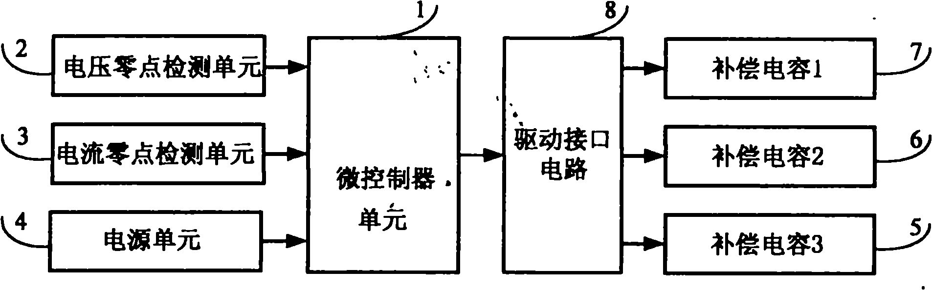
[0015] The principle of the low-power fully intelligent on-site reactive power compensation device of the present invention is as follows:

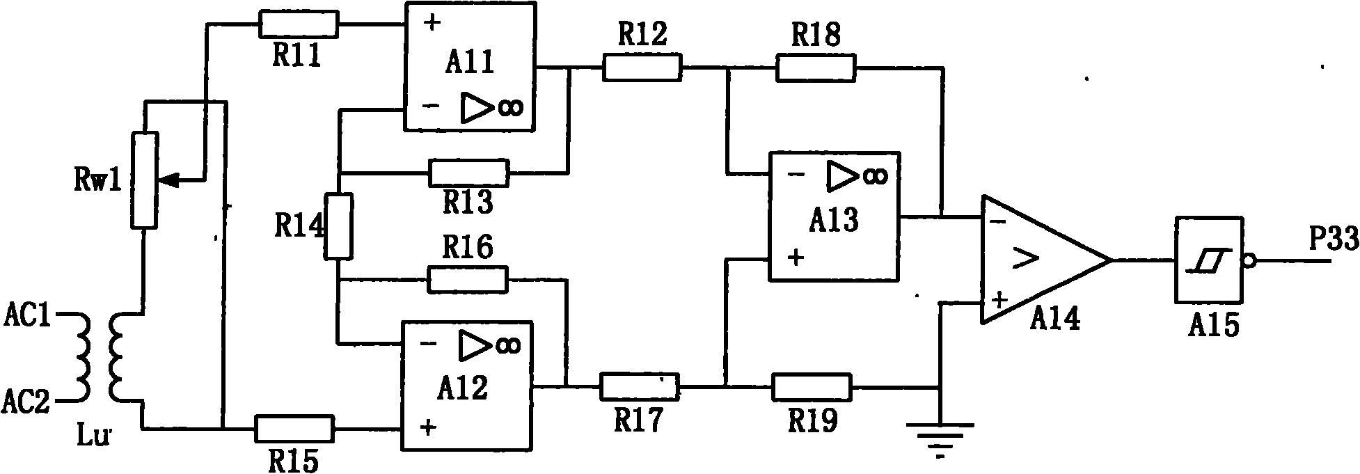
[0016] figure 2 It is the voltage zero point detection circuit diagram of the low-power fully intelligent on-site reactive power compensation device. The primary side of the voltage transformer Lu connected in parallel at both ends of the load obtains the voltage signal of the load, and the secondary output is connected to the potentiometer Rw1 for signal amplitude adjustment, and the center tap of Rw1 is connected to the operational amplifier A11 and A11 through the input resistors R11 and R15. The non-inverting input terminal of A12 suppresses the common-mode signal and amplifies the differential-mode signal, and then inputs it to the input terminal of the operational amplifier A13 to amplify the signal amplitude. The output of A13 is connected to the input terminal of comparator A14 to compare with the zero voltage. When the power fr...


PUM


Abstract

The invention relates to a low-power full-intelligent in-situ reactive power compensation device which comprises a micro-controller unit, a current zero-crossing detection unit, a voltage zero-crossing detection unit, a compensation capacitor switching interface unit and three groups of compensation capacitors, wherein the voltage zero-crossing detection unit is used for carrying out detection on a voltage zero point via a voltage transformer, the current zero-crossing detection unit is used for carrying out detection on a current zero point via a current transformer, zero-crossing signals of voltage and current are connected into a port of the micro-controller unit, the phase difference between the current and the voltage is obtained through the comparison and the calculation in the micro-controller for measuring a power factor, and the compensation capacitors are connected into two ends of a load at the time that the voltage crosses the zero point according to the phase difference between the current and the voltage. The product can be embedded into an electric energy meter or an inductive household electrical appliance as a component part of the electric energy meter or the inductive household electrical appliance, thereby carrying out in-situ reactive compensation on the electrical appliance and achieving the best energy-saving effect.

Description

technical field [0001] The invention relates to a low-power fully intelligent on-site reactive power compensation device, which is used for low-power on-site reactive power compensation in rural areas. It belongs to the automatic control field of energy saving, consumption reduction and power grid power quality optimization. technical background [0002] Reactive power in the grid is compensated centrally in the primary transformer and secondary transformer distribution. Due to the compensation cost and other reasons, reactive power compensation is not performed for the terminal distribution lines with a large number and small wire diameters, and the line loss caused by reactive power is very large. In reactive power compensation, the closer to the end user, the better the energy saving effect of the compensation. With the improvement of living standards in our country, the power consumption of household users has increased significantly, and high-power electrical applianc...

Claims


Application Information

Patent Timeline
Patent Type & Authority Applications(China)
IPC IPC(8): H02J3/18
CPCY02E40/30H02J3/1821H02J2310/20
Inventor 陈靖医
Owner 陈靖医
Why Eureka
Try Eureka