
Method for realizing matching between uplink transmission rate and downlink transmission rate as well as BBU and RRU

A technology of transmission rate and optical transmission, applied in transmission system, digital transmission system, network topology, etc., can solve problems such as price increase, optical module rate increase, uplink and downlink transmission rate mismatch, etc., to improve reliability and reduce data volume and cost reduction

Active Publication Date: 2010-12-29
ZTE CORP
View PDF0 Cites 39 Cited by
  • Summary
  • Abstract
  • Description
  • Claims
  • Application Information

AI Technical Summary

Problems solved by technology

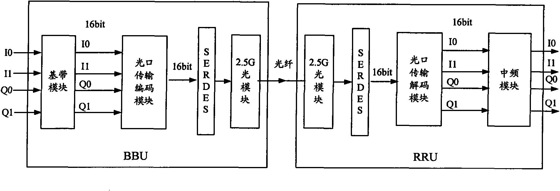
[0010] Since the uplink and downlink transmission rates of distributed base stations do not match under the configuration of nTmR (m=2n), in order to complete the transmission of uplink and downlink IQ data at the same time, it is necessary to select high-speed optical modules based on high transmission rates. The module rate increases by multiples, and the price also increases by multiples, which makes the product cost unable to be effectively controlled, and also reduces the reliability of the hardware design

Method used


Image

  • Method for realizing matching between uplink transmission rate and downlink transmission rate as well as BBU and RRU
  • Method for realizing matching between uplink transmission rate and downlink transmission rate as well as BBU and RRU
  • Method for realizing matching between uplink transmission rate and downlink transmission rate as well as BBU and RRU

Examples


Embodiment Construction

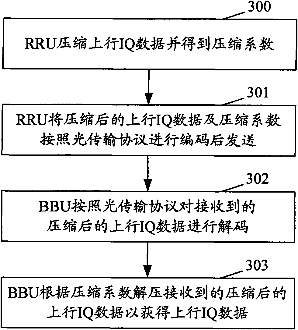
[0045] image 3 It is a flow chart of the method for realizing uplink and downlink transmission rate matching in the present invention, such as image 3 shown, including the following steps:

[0046] Step 300: The RRU compresses the uplink IQ data and obtains a compression factor.

[0047] There are many ways to compress the uplink IQ data in this step, such as existing lossless compression algorithms and lossy compression algorithms, as long as the transmission rate of the compressed uplink IQ data can be guaranteed to be the same as the transmission rate of the current downlink IQ data Matching means to ensure that the uplink and downlink transmission rates in the distributed base stations are equal, and at the same time, the system performance indicators can meet the requirements. Specifically how to achieve compression and how to obtain the compression factor belongs to the usual technical means of those skilled in the art, and will not be repeated here, nor is it used t...


PUM


Abstract

The invention provides a method for realizing matching between uplink transmission rate and downlink transmission rate of a distributed base station, as well as a building baseband unit (BBU) and a remote radio unit (RRU), and a method for transmitting uplink data by the RRU and a method for receiving uplink data by the BBU. Before being transmitted by the RRU, the uplink IQ data is compressed toreduce the data volume of uplink transmission so as to match the compressed uplink transmission rate and the downlink transmission rate and ensure that optical modules selected by using the transmission rate of uplink fibers as a standard can be suitable for the transmission rate of uplink transmission fibers, thereby reducing the cost of optical modules and simultaneously improving the reliability of hardware circuit design.

Description

technical field [0001] The present invention relates to a distributed base station transmission technology, especially a method for a distributed base station to realize uplink and downlink transmission rate matching, an indoor baseband processing unit (BBU, Building Baseband Unit) and a radio frequency remote unit (RRU, Remote Radio Unit), and A method for the RRU to send uplink data and a method for the BBU to receive uplink data. Background technique [0002] At present, the distributed base station of BBU+RRU is widely used in the WIMAX (Worldwide Interoperability for Microwave Access) system, and the distributed base station will also be used in the next-generation broadband mobile communication long-term evolution standard (LTE, Long Term Evolution) system has been popularized and applied. [0003] The calculation method of the transmission rate of baseband data between BBU and RRU, that is, IQ data (wherein, I is the same direction component and Q is the quadrature c...

Claims


Application Information

Patent Timeline
IPC IPC(8): H04W28/06H04W28/22H04W84/12H04W88/08H04L1/00
Inventor 周敏王永贵
Owner ZTE CORP
Learn More