Supercharge Your Innovation With Domain-Expert AI Agents!

Measuring equipment and amplifying circuit, impedance component and multilayer printed circuit board thereof

A multi-layer printing and circuit board technology, applied in the field of resistance network or multi-layer printed circuit board, amplifying circuit, can solve the problems of temperature characteristics matching, equipment application, mass production difficulties, and difficult to find compensation capacitors, etc.

Active Publication Date: 2010-12-29
RIGOL
View PDF0 Cites 3 Cited by
  • Summary
  • Abstract
  • Description
  • Claims
  • Application Information

AI Technical Summary

Problems solved by technology

However, it is very difficult to implement because of:
[0049] 1. Due to the change of temperature, the dielectric constant of the dielectric layer of the above-mentioned printed circuit board will change by up to 20%, which makes it impossible to accurately determine the size of the compensation capacitor
Therefore, when using this method to compensate for parasitic capacitance, some people design the compensation capacitor as an adjustable capacitor, but this will bring difficulties to the application of equipment and mass production.
In order to solve the influence of temperature on printed circuit boards, some people choose materials with stable dielectric constants to make printed circuit boards, but this method has the disadvantages of high cost or difficult processing.
[0050] 2. The capacitance value of the usual capacitive element is discontinuous, and there is a tolerance between the nominal data and the actual data. Sometimes it is difficult to find a compensation capacitor that is exactly equal to the parasitic capacitance
[0051] 3. The capacitive element itself as a compensation capacitor also has temperature characteristics, and its temperature characteristics are often difficult to match with the temperature characteristics of the parasitic capacitance of the printed circuit board

Method used


Image

  • Measuring equipment and amplifying circuit, impedance component and multilayer printed circuit board thereof
  • Measuring equipment and amplifying circuit, impedance component and multilayer printed circuit board thereof
  • Measuring equipment and amplifying circuit, impedance component and multilayer printed circuit board thereof

Examples


no. 1 example

[0236] refer to Figure 12 , in this embodiment, the measuring device of the present invention is a digital multimeter 200, and the digital multimeter 200 includes an input terminal 202, a range amplification circuit 201, an A / D converter 204 and a microprocessor 205. The input terminal 202 is used to connect the external measured signal, the range amplifier circuit 201 is used to perform signal amplification processing on the measured signal from the input terminal 202, and the A / D converter 204 is used to simulate the output signal of the range amplifier circuit 201. For digital conversion, the microprocessor 205 is used to process the digital signal output by the A / D converter 204.

[0237] As an example, in this embodiment, other circuits may be included between the input terminal 202 and the range amplification circuit 201, such as an overvoltage and overcurrent protection circuit, an attenuation circuit, and the like. Other circuits may also be included between the rang...

no. 2 example

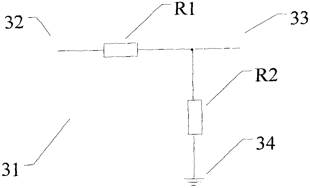
[0270] In this embodiment, the measuring equipment described in the present invention is an oscilloscope 600, please refer to Figure 26, the oscilloscope 600 includes an amplifying circuit 601 , and the amplifying circuit 601 is connected in series to the input circuit of the oscilloscope 600 through an input terminal 611 and an output terminal 612 . In this amplifier circuit there is a resistor network 602 connected in series between an input terminal 611 and an output terminal 612 and an operational amplifier A61. Among them, the resistor network 602 is an attenuation network composed of a resistor R61 and a resistor R62, which is mainly used to attenuate the incoming measured signal. One end of the resistor R61 is connected to the input terminal 611, and the other end is connected to the positive input of the amplifier A61. One end of the resistor R62 is connected to the positive input end 614 of the amplifier A61, and the other end is connected to the common end 613. In ...


PUM


Abstract

The invention provides measuring equipment and an amplifying circuit, an impedance component and a multilayer printed circuit board thereof, relating to a multilayer printed circuit board 220, a first resistor R21 and a second resistor R22, wherein the multilayer printed circuit board 220 is provided with an element layer 221, an insulating layer 224, an insulating layer 225 and a shielding layer 223; and the element layer 221 is provided with a first pad 231, a second pad 232 and a third pad 233 which are used for mounting the first resistor R21 and the second resistor R22. An intermediate layer 222 is arranged in the multilayer printed circuit board 220, so that the invention can weaken or remove the parasitic capacitors C23, C24 and C25 introduced by the pads 231 and 232 by changing the sizes of the first pad 231, the second pad 232 and the intermediate layer 222 and the thickness and / or the dielectric constants of the insulating layers 224 and 225, thus improving the frequency characteristics of the circuit, and the invention has the characteristics of stable performance, simple design and easy realization.

Description

technical field [0001] A measuring device and its amplifying circuit, impedance component and multilayer printed circuit board of the present invention relate to the field of electric variable measuring device and its adopted amplifying circuit, resistance network or multilayer printed circuit board. Background technique [0002] With the popularization and development of surface mount technology (SMT), the manufacturing process level of the current measurement equipment has been greatly improved, and the structure of the measurement equipment is more compact and small. But at the same time, this process technology also brings the problem of parasitic capacitance to the measurement equipment, especially in the case of setting a shielding layer (ground layer) on the printed circuit board in order to eliminate electromagnetic interference, this problem becomes even more serious. The reason for this is that parasitic capacitances are formed between the pads on the component lay...

Claims


Application Information

Patent Timeline
IPC IPC(8): H05K1/00H05K1/11H05K9/00H01C1/16G01R15/12G01R13/00
Inventor 王悦王铁军李维森
Owner RIGOL
Features
  • R&D
  • Intellectual Property
  • Life Sciences
  • Materials
  • Tech Scout
  • Unparalleled Data Quality
  • Higher Quality Content
  • 60% Fewer Hallucinations
Learn More