Heat exchanger

A heat exchanger and header technology, applied in the field of parallel-flow heat exchangers, can solve the problems of increasing the space of the heat exchanger 1, difficult to achieve equalization of refrigerant flow, and reduction of refrigerant flow, etc., so as to achieve equal refrigerant flow. the effect of

Active Publication Date: 2012-09-19
SHARP KK
View PDF2 Cites 0 Cited by
  • Summary
  • Abstract
  • Description
  • Claims
  • Application Information

AI Technical Summary

Problems solved by technology

However, the refrigerant R with such upward kinetic energy cannot reach the flat tube 4 leaving the center, resulting in a decrease in the refrigerant flow rate
That is, it is difficult to equalize the refrigerant flow rate
In addition, since the inlet pipe 7 protrudes downward from the lower side of the lower header pipe 2, it is necessary to raise the height of the heat exchanger 1 so that the inlet pipe 7 does not come into contact with the components located below the heat exchanger 1 (storing the heat exchanger 1). bottom plate of the housing, etc.), thereby increasing the space required for setting the heat exchanger 1

Method used


Image

  • Heat exchanger
  • Heat exchanger
  • Heat exchanger

Examples


Embodiment Construction

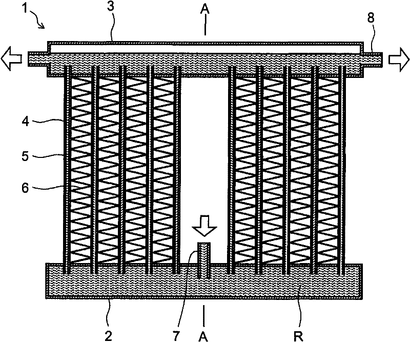
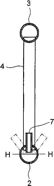
[0052] The following is based on figure 1 , figure 2 A first embodiment of the present invention will be described. Since the heat exchanger 1 of the first embodiment has many parts and Figure 16 The conventional structure shown is the same, so the same part adopts the same Figure 16 The same reference numerals are used, and repeated explanations are omitted. The first embodiment and Figure 16 The difference of the conventional structure is the arrangement method of the inlet pipe 7. The inlet pipe 7 is arranged away from the outlet pipe 8 . Since the outlet pipe 8 is located at both ends of the upper header 3 , the central portion of the lower header 2 is located away from the outlet pipe 8 . Although so far with Figure 16 However, in the present invention, instead of connecting the inlet pipe 7 to the lower header pipe 2 from below, it is connected to the lower header pipe 2 from above. In addition, in order to avoid interference between the inlet pipe 7 and th...


PUM


Abstract

A parallel flow type heat exchanger (1) in which flow rates of refrigerant are equalized for respective flat tubes (4). The heat exchanger (1) comprises a lower header pipe (2) becoming the refrigerant inflow side, an upper header pipe (3) becoming the refrigerant outflow side, and a plurality of vertical flat tubes (4) arranged at a predetermined pitch, between both the header pipes (2, 3), and each having a vertical refrigerant passage (5) provided therein and communicating with the inside of both the header pipes. An inlet pipe (7) for making the refrigerant (R) flow into the lower header pipe (2) is arranged between a pair of flat tubes (4) out of a plurality of flat tubes (4), spaced apart from an outlet pipe (8) for making the refrigerant flow out from the upper header pipe (3) and connected with the lower header pipe (2) from the above. The outlet pipes (8) are provided at the both ends of the upper header pipe (3), and the inlet pipe (7) is arranged between the pair of flat tubes (4) located in the center of the lower header pipe (2).

Description

technical field [0001] The present invention relates to parallel flow heat exchangers applied to air conditioners or refrigeration equipment. Background technique [0002] A parallel-flow heat exchanger widely used in automobile air conditioners, etc., the parallel-flow heat exchanger is equipped with a plurality of vertical flat tubes between the upper and lower main tubes, and the refrigerant passage inside the flat tubes is connected with the two The internal communication of the root duct. For this example, Patent Document 1 (Japanese Patent Publication No. 3133897) and Patent Document 2 (Japanese Utility Model Laid-Open Publication No. Hei 6-14782) can be referred to. [0003] In parallel-flow heat exchangers, the key to improving heat exchange performance is to equalize the refrigerant flow in each flat tube. In the parallel-flow heat exchangers described in Patent Documents 1 and 2, equalization of the flow rates of the refrigerants in the flat tubes is achieved as ...

Claims


Application Information

Patent Timeline
Patent Type & Authority Patents(China)
IPC IPC(8): F28F9/02F25B39/02F28D1/053F28F9/22
CPCF28F9/0246F28D1/05375F28D2001/028
Inventor 上野円
Owner SHARP KK
Why Eureka
Try Eureka